Glow-worm Hideaway 100C FF Instructions For Use Installation And Servicing Download Page 23

23

0020003579A

7  Instructions to the User

Instruct and demonstrate the safe and efficient operation of the boiler, heating system and domestic hot water system.

Advise the user, that to ensure the continued efficient and safe operation of the boiler, it is recommended that it is checked and
serviced at regular intervals.  The frequency of servicing will depend upon the particular installation and usage, but in general once
a year should be enough.

Draw attention, if applicable to the current issue of the Gas Safety (Installation and Use) Regulations, Section 35, which imposes
a duty of care on all persons who let out any property containing a gas appliance in the UK.

It is the Law that servicing is carried out by a 

competent person

.

Advise the user of the precautions necessary to prevent damage to the system and building in the event of the heating system being
out of use during frost and freezing conditions.

Reminder - Leave these instructions and the “Benchmark” logbook with the user.

8  Servicing

REMEMBER, When replacing a part on this appliance, use only
spare parts that you can be assured conform to the safety and
performance specification that we require. Do not use
reconditioned or copy parts that have not been clearly authorised
by Glow-worm

Products of Combustion Check
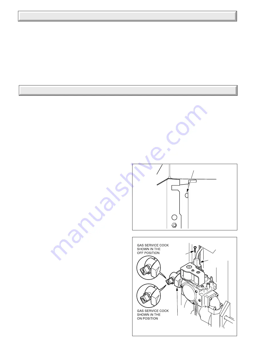
NOTE:

 To obtain a products of combustion reading, remove the

front panel, see diagram 6.3 and remove the control box as
described in the relevant paragraphs of section 4.9.   Next,
remove the cap from the sampling point, located on the top of
the left hand side of the inner casing, see diagram 8.1.

Connect the analyser tube on to the nipple.

WARNING:

  The multifunctional control and fan operate on

mains voltage, terminals will become live.

Switch on the electrical supply and gas supply then operate the
boiler.

On completion of the test switch off the electrical supply and gas
supply, remove analyser tube and replace sampling point cap.

Servicing

Before servicing turn off the gas and isolate the electrical supply
to the boiler.

After completing a service always test for gas soundness, make
electrical checks and carry out functional check on controls.

Unless stated otherwise all parts are replaced in the reverse
order to removal.

8.1 Access

Remove the boiler front casing panel, refer to paragraph 6.8.

Remove the bottom plinth panel by unscrewing the two dog
point screws securing the panel to the boiler plinth, see diagram
8.4.

Disconnect gas valve from gas cock and unplug electrical plug
from gas valve, firstly removing electrical plug securing screw,
see diagram 8.2.

Unclip electrical wires from control box support bracket, see
diagram 8.3.

Undo the five self-tapping screws that secure the combustion
chamber front and carefully withdraw it together with the burner
and gas valve assembly, taking care not to strain the ignition,
sensing and earth leads, see diagram 8.5.

NOTE:

 When replacing burner in combustion chamber make

sure it fits correctly on the guides.

Diagram 8.2

12165

GAS SERVICE
COCK UNION

Diagram 8.1

Disconnect the ignition, sensing and earth leads from the
burner and remove by drawing the leads though the grommet,
see diagram 8.5 and 8.9.

Remove the three self-tapping screws from the lower part of the
control box support bracket, see diagram 8.6.

Undo the wing nut that secures the top of the heat shield and
carefully hinge down control box and heat shield, see diagram
8.6.

Release the three toggle latches that secure the boiler access
door and remove, see diagram 4.10.

SECURING
SCREW

12091

SAMPLE POINT

ELECTRICAL
PLUG

Summary of Contents for Hideaway 100C FF

Page 1: ...r Instructions for Use Installation and Servicing G C No 41 047 42 Chimney Fanned Flue Boiler 0020003579A 08 04 Hideaway 100C FF G C No 41 047 43 Hideaway 115C FF Glow worm Nottingham Road Belper Derb...

Page 2: ...ance in your home Glow worm appliances are manufactured to the very highest standard so we are pleased to offer our customers a Comprehensive First Year Guarantee We recommend you complete and return...

Page 3: ...o the User 7 23 Servicing 8 23 Fault Finding 9 26 Replacement of Parts 10 29 Spare Parts 11 31 CONTENTS DESCRIPTION SECTION PAGE No INSTRUCTIONS FOR USE INSTALLATION INSTRUCTIONS SERVICING INSTRUCTION...

Page 4: ...follow normal good hygiene and wash your hands before eating drinking or going to the lavatory If you do suffer irritation to the eyes or severe irritation to the skin seek medical attention The insu...

Page 5: ...ination Manufacturer s instructions must not be taken as overriding statutory requirements These instructions should be carefully followed for the safe and economical use of your boiler NOTE The boile...

Page 6: ...ion using the telephone number on the inside front cover of this literature Please be advised that the Benchmark logbook should be completed by the installation engineer on completion of commissioning...

Page 7: ...or any remote control NOTE If the boiler is turned OFF at the boiler temperature control wait at least 30 seconds before switching on again When the boiler switches off the burner will go out The aut...

Page 8: ...the rules in force In GB the installation of the boiler must be carried out by a competent person as described in the following regulations The manufacturer s instructions supplied The Gas Safety Inst...

Page 9: ...th the current issue of BS6891 1 6 Electrical WARNING This boiler must be earthed The electrical installation must be carried out by a competent person All external components shall be of the approved...

Page 10: ...clearance required will vary with site conditions When the boiler is to be installed level with work surfaces and the like minimum clearances should be provided as shown in diagram 1 5 Work tops whic...

Page 11: ...ST NOT BE REDUCED IF A GRILLE IS FITTED CUPBOARD CUPBOARD 406cm2 FREE AREA FOR VENTILATION 11601 2 Water Systems The installation of the boiler must comply with the requirements of the current issue o...

Page 12: ...t3in must be provided between the water line of the feed tank and the centre of the waterway see diagram 2 2 2 5 Circulation Pump Normallythepumpshouldbesettogiveatemperaturedifference of11o C 20o F a...

Page 13: ...himney top must be adequately sealed and clamped using proprietary fittings suitable for the flue liner used see diagram 3 1 The flue should preferably end above ridge height but at the least above th...

Page 14: ...must have minimum areas see Compartment Air Vent table Thefiguresquotedrefertotheminimumacceptable effective area Both the high and low level openings must communicate with the same room or must both...

Page 15: ...may be used for the gravity domestic hot water return Fit plugs into any unused boiler tappings 4 3 Water Connections Fully Pumped Systems Fit suitable fittings into the boiler tappings as required se...

Page 16: ...pipework must be along the left hand side of the boiler 4 Installation No 8 SCREW 4 Diagram 4 4 PIPEWORK CASING CLEARANCES 9860 Diagram 4 6 4 6 Casing Brackets Fit the two upper and two front casing...

Page 17: ...e control box and heat shield fitted in the lower casing height position 4 8 Side Casings Fit the side casings by locating their lugs into the appropriate slot in the boiler plinth see diagram 4 7 dep...

Page 18: ...usly removed screw To connect a condensate drain remove plastic end stop by depressing the collet Slide the Chimney Flue Adapter into the flue spigot until it engagesinthebayonetconnection thentwistcl...

Page 19: ...drain should be fitted To use the condensate drain connection on the chimney flue adapter remove the end stop see diagram 4 13 A 22mm plastic overflow pipe should be used to fit on to the drain connec...

Page 20: ...ng connections make sure that the earth conductor ismadeofagreaterlength thanthecurrentcarryingconductors so that if the cable is strained the earth conductor would be the last to become disconnected...

Page 21: ...ENTS 10052 A CONTROL BOX B PHIAL POCKET C GAS SERVICE COCK D BURNER ON INDICATOR E RESET STANDBY INDICATOR F TEMPERATURE CONTROL G BURNER PRESSURE TEST POINT H GAS PRESSURE ADJUSTMENT SCREW J DATA LAB...

Page 22: ...ontrol fully anti clockwise to 0 Isolate from the electrical supply Remove the pressure gauge from the test point and refit screw making sure a gas tight seal is made When the boiler temperature contr...

Page 23: ...erate on mains voltage terminals will become live Switch on the electrical supply and gas supply then operate the boiler On completion of the test switch off the electrical supply and gas supply remov...

Page 24: ...the retaining lugs then lift up When replacing the flue hood ensure that it rests on the guides and that the rear of flue hood is located under the pegs at the rear and pushed down and back fully IMP...

Page 25: ...g the relevant instructions in sections 8 3 and 8 4 8 3 Burners and Injectors Remove the screws and nuts securing the burner support bracket to the combustion chamber cover see diagram 8 9 Remove the...

Page 26: ...external controls are calling for heat and circuit water is cold If Reset Standby indicator is lit check water system for overheating reset by turning temperature control knob off and on If the indic...

Page 27: ...to section 5 1 Refer to Boiler Fault Finding see diagram 9 1 Fault Finding Wiring Diagram see diagram 9 3 Pictorial Wiring Diagram see diagram 9 4 9 2 Electrical Supply Failure Failure of the electric...

Page 28: ...EEN YELLOW g GREY bk BLACK p PURPLE r RED w WHITE FAN Ls LIVE Switched N NEUTRAL EARTH MAIN KEY TO TERMINAL BLOCK KEY b b b b b b p r g g r p bk bk bk bk bk g y g y g y g y br br br bk AIR PRESSURE SW...

Page 29: ...on the heat shield and lift off see diagram 10 1 Carefully pull the boiler temperature control knob away from the P C B Disconnect the electrical plugs from the control board PCB slightly bending bac...

Page 30: ...phs of Section 8 servicing to remove the burner from combustion chamber Remove the electrical connections and air pressure tubes from the fan NOTE Remove the electrical connections by pulling insulati...

Page 31: ...njector 100C FF 8 205746 Injector 115C FF 9 202240 Fuse 10 2000461896 Control board 11 205657 Double Burner 11 1 Part Identification The key number in diagram 11 1 and the first column of the list wil...

Page 32: ...32 0020003579A Because of our constant endeavour for improvement details may vary slightly from those shown in these instructions...

Reviews: