18
9.
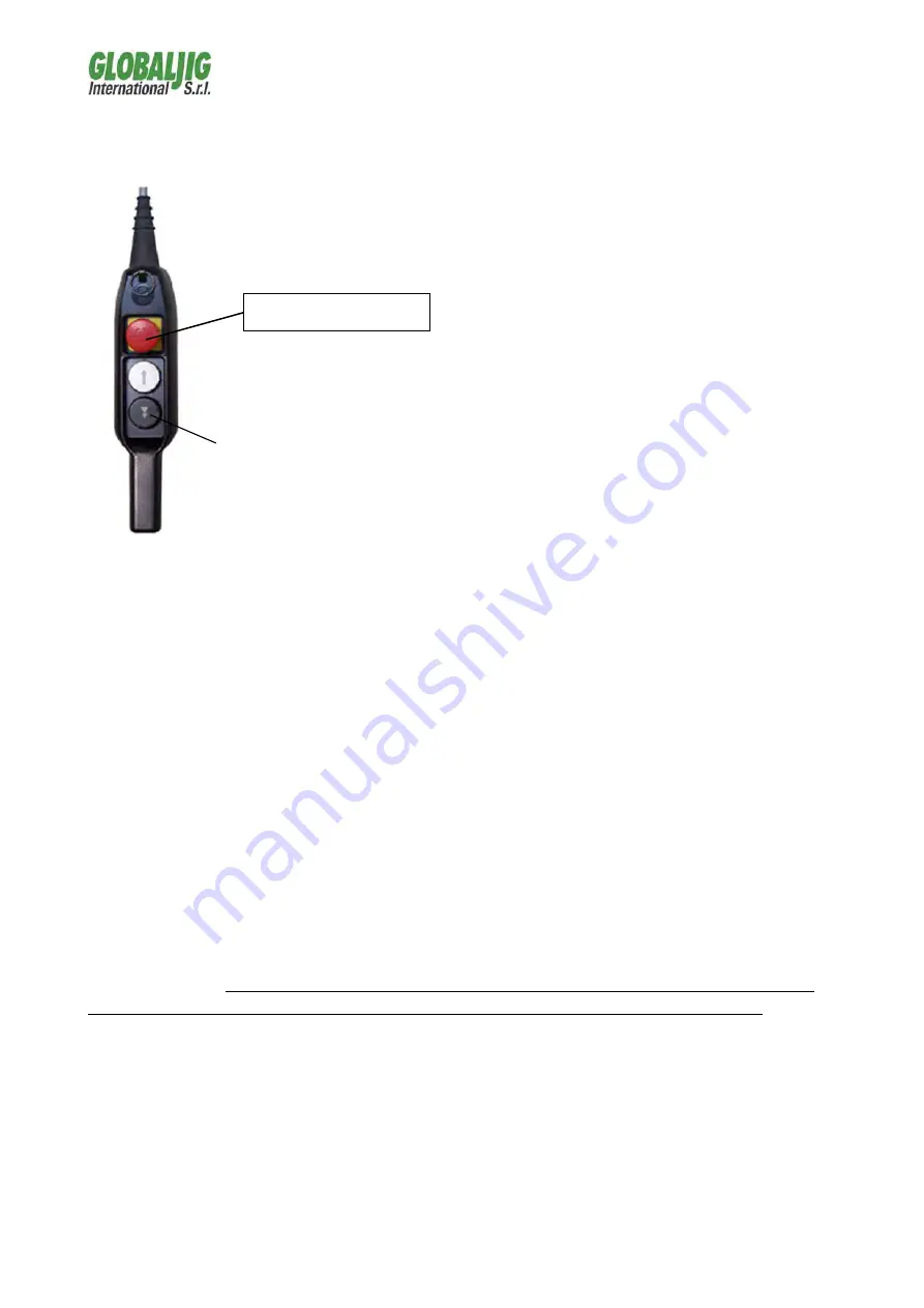
RAISING AND LOWERING THE HYDRAULIC POWER LIFT
After connecting the unit to
its electrical power and
compressed air supplies, turn
the switch on the mobile
control unit and engage the
emergency button on the
button panel.
After opening the load
support by means of their
relative command, the lifting
pads are to be positioned and
their thickness chosen
according to the requirements
(vehicle bottom). Press the
raise button again to raise the
load to the desired height.
The hydraulic power lift has a mechanical safety spear device which is
always on, while a total closure valve positioned directly upon the lifting
jacks will impede the lift from lowering at all times due to any eventual (and
improbable) air-pressure supply tube ruptures.
In order to lower the load, if the hydraulic power lift is in safe conditions,
raise the platform a few inches to release the safety catch then press the
lower button until the platform has descended completely.
The lower button is equipped double action: The first opens the discharge
valve, while the second sends air to the safety catch device in order to
disengage it.
This functionality allows for the hydraulic power lift to be placed in safe
conditions once the desired height has been reached; in fact, by lightly
pressing the lower button, the discharge valve opens and the lift descends
until the safety catch device engages within the its lodgings on the base,
thereby impeding further descent.
ATTENTION: When working upon the vehicle, the hydraulic power lift must
be placed in safe conditions by following the procedure described above.
Before and during all manoeuvres, always act in an attentive manner, while
checking the stability of the load.
After the descent has been completed, or rather, when the vehicle is resting
upon the floor on its wheels and the lift pads are no longer in contact with
the vehicle, release the lower button, remove the lifting pads and close the
arms.
Emergency button
LOWER button
Safety deactivation button
Summary of Contents for Quick Pull
Page 1: ......
Page 2: ......
Page 6: ...6 2 2 Quick Pull Hydraulic Power Lift encumbrance dimensions ...
Page 16: ...16 7 8 9 RIF CODE DESCRIPTION 7 GK3 CONTACTOR 8 GK4 TRANSFORMER 9 GK5 CIRCUIT ...
Page 25: ...25 17 ANNEXES ...
Page 26: ...26 ...
Page 27: ...27 ...
Page 28: ...28 ...
Page 29: ...29 ...
Page 30: ...30 ...
Page 31: ...31 ELECTRICAL SYSTEM SCHEME ...
Page 32: ...32 ELECTRONIC BOARD ...
Page 33: ...33 HYDRAULICS SYSTEM SCHEME ...
Page 36: ......
Page 37: ......


