background image

                                                                                      4 


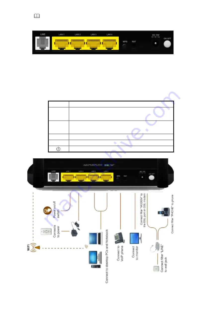
Step 2 

Connect the 

LAN

 interface of the device to the network card of the PC through an Ethernet cable (MDI/MDIX). 

    Note: 

Use twisted-pair cables to connect with the hub or switch. 


Step 3 

Plug one end of the power adapter to the wall outlet and connect the other end to the 

Power


interface of the device. 

Installing a telephone directly before the splitter may lead to failure of connection between the device and the central office, or 

failure of Internet access, or slow connection speed. If you really need to add a telephone set before the splitter, you must add 

a microfilter before a telephone set. Do not connect several telephones before the splitter or connect several telephones with 

the microfilter. 


Port 

Function 

DSL 

Connects the device to an ADSL telephone jack or splitter using a RJ-11 

telephone cable 

LAN 

Connects the device to your PC's Ethernet port, or to the uplink port 

on your hub/switch, using a RJ-45 cable 

Reset 

System reset or reset to factory defaults. 

POWER 

Connects to the supplied power adapter 


Switches the unit on and off 


Summary of Contents for MSW300Np4

Page 1: ...ons and makes no warranty or representation either expressed or implied with respect to the quality performance merchantability or fitness for a particular purpose of the software or documentation Glo...

Page 2: ...verheating to the device The long and thin holes on the device are designed for heat dissipation to ensure that the device works normally Do not cover these heat dissipation holes Do not put this devi...

Page 3: ...of service QoS Remote access control Line connection status test Remote managing through Telnet or HTTP Backup and restoration of configuration file Ethernet interface supporting crossover detection...

Page 4: ...ee interfaces Line Connect to a wall phone jack RJ 11 jack Modem Connect to the ADSL jack of the device Phone Connect to a telephone set LED Color Function PWR Green On Power Off No power or system bo...

Page 5: ...office or failure of Internet access or slow connection speed If you really need to add a telephone set before the splitter you must add a microfilter before a telephone set Do not connect several te...

Page 6: ...E browser and enter http 192 168 1 1 Step 5 In the Login page that is displayed enter the username and password The username and password of the super user are admin and admin The username and passwor...

Page 7: ...d shows the current status and some basic settings of the router such as software version DSP version uptime upstream speed and downstream speed LAN Choose Status LAN The page that is displayed shows...

Page 8: ...some basic settings of wireless LAN WLAN WAN Choose Status WAN The page that is displayed shows some basic WAN settings of the router In this page you can view basic status of WAN and DNS server If yo...

Page 9: ...of port mapping Statistics Choose Status Statistics The Statistics page that is displayed contains Traffic Statistic and ADSL Statistic Traffic Statistic Click Traffic Statistic in the left pane The p...

Page 10: ...ge shown in the following figure appears In this page you can view the ADSL line status upstream rate downstream rate and other information ARP Table Choose Status ARP Table In the ARP Table page you...

Page 11: ...navigation bar choose Wizard The page shown in the following figure appears The following table describes the parameters in this page Field Description VPI Virtual path identifier VPI is the virtual p...

Page 12: ...ress for PPPoE connection Use the following IP address Select it you need to enter the IP address for PPPoE connection which is provided by your ISP Enable NAT Select the checkbox to enable network ad...

Page 13: ...8 1 1 to 192 168 255 254 The default IP address is 192 168 1 1 LAN Netmask Enter the subnet mask of LAN interface Its valid value is in the range of 255 255 0 0 to 255 255 255 254 Enable Secondary IP...

Page 14: ...Enter the start IP address that the DHCP sever assigns After setting click Next the page as shown in the following figure appears Click BACK to modify the settings Click FINISH to save the settings C...

Page 15: ...ain DNS server addresses automatically Select it DHCP automatically assigns DNS server address Use the following DNS server addresses Select it you need to manually enter the primary DNS server addres...

Page 16: ...alue is in the range of 255 255 0 0 to 255 255 255 254 Enable Secondary IP Select the checkbox to enable the secondary LAN IP The two LAN IP addresses must be in the different network DHCP Server Enab...

Page 17: ...the settings Click RESET to cancel the settings Note If the WAN connection type is set to 1483 Routed the parameters of the WAN connection type are the same as that of 1483 MER For the parameters in t...

Page 18: ...N Netmask Enter the subnet mask of LAN interface Its valid value is in the range of 255 255 0 0 to 255 255 255 254 Enable Secondary IP Select the checkbox to enable the secondary LAN IP The two LAN IP...

Page 19: ...nel Configuration page do not take effect any more Network In the navigation bar click Network The Network page displayed contains LAN WAN and WLAN LAN Choose Network LAN The LAN page that is displaye...

Page 20: ...Mbps Half Duplex 10Mbps FullDuplex 10Mbps Half Duplex Auto Negotiation MAC Address Control It is the access control based on MAC address Select it and the host whose MAC address is listed in the Curre...

Page 21: ...CP server DNS Servers You can configure the DNS server ip addresses for DNS Relay Set VendorClass IP Range Click it the Device IP Range Table page appears You can configure the IP address range based...

Page 22: ...21 In the DHCP Mode field choose None The page shown in the following figure appears...

Page 23: ...ic IP in the left pane the page shown in the following figure appears You can assign the IP addresses on the LAN to the specific individual PCs based on their MAC address The following table describes...

Page 24: ...function If you do not select it and you want to access the Internet normally you must add a route on the uplink equipment Otherwise the access to the Internet fails Normally it is enabled Enabel IGM...

Page 25: ...his PVC Current ATM VC Table This table shows the existed PVCs It shows the interface name channel mode VPI VCI encapsulation mode local IP address remote IP address and other information The maximum...

Page 26: ...o enable the MAC Clone function with the MAC address that is configured ATM Setting Click ATM Setting in the left pane the page shown in the following figure appears In this page you can configure the...

Page 27: ...Basic Setting and the following page appears In this page you can configure the parameters for wireless LAN clients that may connect to the modem The following table describes the parameters of this p...

Page 28: ...it to apply the settings temporarily If you want to save the settings of this page permanently click Save in the lower left corner Security Choose WLAN Security and the following page appears The foll...

Page 29: ...racters If you choose 128 bit you can choose ASCII 13 characters or Hex 26 characters Default Tx Key Choose the index of WEP Key You can choose Key 1 Key 2 Key 3 or Key 4 Encryption Key 1 to 4 The Enc...

Page 30: ...e 64 bit and ASCII 5 characters enter any 5 ASCII characters If you choose 64 bit and Hex 10 characters enter any 10 hexadecimal characters If you choose 128 bit and ASCII 13 characters enter any 13 A...

Page 31: ...s isolation Select Enable the wireless clients that are connected to the modem can not intercommunication Ethernet to Wireless Blocking Whether the wireless network can communicate with the Ethernet n...

Page 32: ...g IP address For example the domain name www example com might be translated to 198 105 232 4 The DNS has its own network If one DNS server does not know how to translate a particular domain name it a...

Page 33: ...e DDNS function Username The name provided by DDNS provider Password The password provided by DDNS provider Email The email provided by DDNS provider Key The key provided by DDNS provider Firewall Cho...

Page 34: ...w yahoo comand and filtered keyword You can add or delete FQDN and filtered keyword The following table describes the parameters and buttons of this page Field Description URL Blocking Capability You...

Page 35: ...he default settings If you select User defined Service Name you need to enter the corresponding parameters Protocol Choose the transport layer protocol that the service type uses You can choose TCP or...

Page 36: ...address will select one IP address from the pool for NAT DMZ Setting Demilitarized Zone DMZ is used to provide Internet services without sacrificing unauthorized access to its local private network T...

Page 37: ...rs In the page you can configure some source IP addresses which use the purge route mode when accessing internet through the specified interface UPNP Choose Service UPnP the page shown in the followin...

Page 38: ...oxy for its hosts after you enable it ACL Choose Service ACL the page shown in the following figure appears In this page you can permit the data packets from LAN or WAN to access the router You can co...

Page 39: ...he specified interface Only the IP address that is in the same network segment with the IP address of the specified interface can access the router Services Allowed You can choose the following servic...

Page 40: ...page Advanced In the navigation bar click Advanced In the Advanced page that is displayed contains Bridge Setting Routing Port Mapping QoS SNMP and Others Bridge Setting Choose Advanced Bridge Settin...

Page 41: ...r the IP address of the next hop in the IP route to the destination device Metric The metric cost for the destination Interface The interface for the specified route Add Route Click it to add the new...

Page 42: ...ttings of this page Interface Choose the router interface that uses RIP Receive Version Choose the interface version that receives RIP messages You can choose RIP1 RIP2 or Both Choose RIP1 indicates t...

Page 43: ...42 Port Mapping Choose Advanced Port Mapping The page shown in the following figure appears In this page you can bind the WAN interface and the LAN interface to the same group...

Page 44: ...quired mapping of the ports Click Apply Changes to save the changes QoS Choose Advanced QoS the page shown in the following figure appears Entries in the QoS Rule List are used to assign the precedenc...

Page 45: ...44...

Page 46: ...The port of the destination data packet Protocol The protocol responds to the IP QoS rules You can choose TCP UDP or ICMP Physical Port The LAN interface responds to the IP QoS rules Set priority The...

Page 47: ...ssword to read the information of this router Community Name Read Write The network administrators must use this password to configure the information of the router Others Choose Advanced Others the p...

Page 48: ...Do not turn off the router or press the Reset button while the procedure is in progress Upgrade Firmware Click Upgrade Firmware in the left pane the page shown in the following figure appears In this...

Page 49: ...ppears In this page you can enable or disable system log function and view the system log Password Choose Admin Password the page shown in the following figure appears By default the user name and pas...

Page 50: ...49 Time Zone Choose Admin Time Zone the page shown in the following figure appears You can configure the system time manually or get the system time from the time server...

Page 51: ...ion bar click Diagnostic The Diagnostic page that is displayed contains Ping ATM Loopback ADSL and Diagnostic Test Ping Choose Diagnostic Ping The page shown in the following figure appears The follow...

Page 52: ...diagnostics Click Start to start ADSL tone diagnostics Diagnostic Test Choose Diagnostic Diagnostic Test the page shown in the following figure appears In this page you can test the DSL connection You...

Reviews: