18
Visit our website at http://www.globalhobby.com or for Customer Service at http://globalservices.globalhobby.com
❑
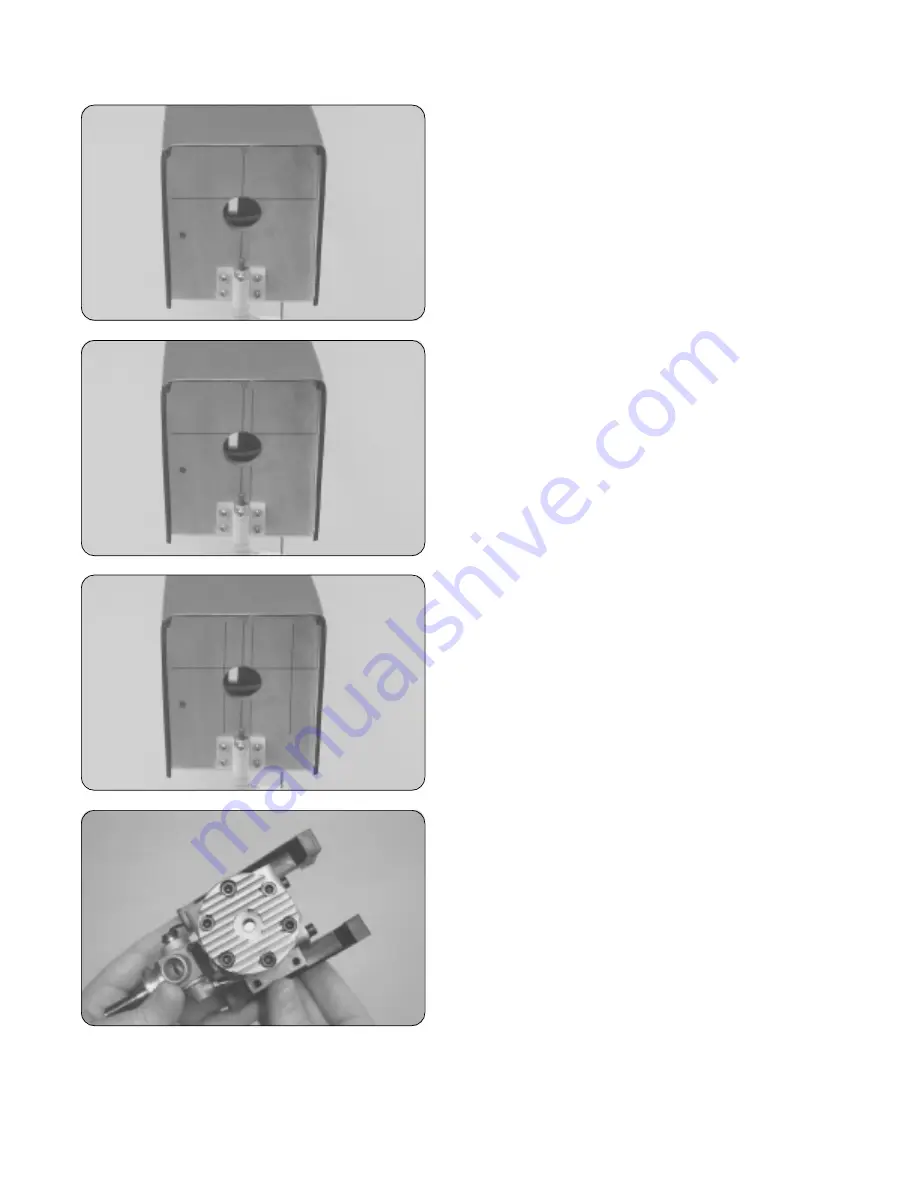
Using a ruler and a pencil, measure 2-7/8"
up
from the
bottom
of the firewall and draw a horizontal line. This line
will be referred to as the "horizontal thrust line."
❑
Measure 1/4" to the
right
of the vertical centerline and
draw a second vertical line parallel to it.
☞
This second vertical line will be referred to as the "vertical
thrust line."
❑
Using a ruler and a pencil, measure and draw a vertical
line 1" to the
right
of the
vertical thrust line
.
❑
Measure and draw a vertical line 5/8" to the
left
of the
vertical thrust line
.
IMPORTANT
Do not measure from the centerline. Measure
from the vertical thrust line.
❑
Temporarily glue the two engine mounting beams to your
engine's mounting lugs using a couple of drops of thick C/A.
☞
The location of the engine is not important at this time.
It's more important that the beams are square to the
mounting lugs.
❑
Using a ruler, measure the distance between the holes in the two engine mounting beams. As an example, for the
Magnum XL .61ARNV engine used in this model, the distance between the holes in the two beams is 2-1/8". Your
measurement may differ if you are using a different size engine. It depends on the width of the engine's crankcase.


