


10
M
AINTENANCE
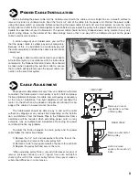
Experience has shown that when only a short section of the power cable is regularly used, the cable may be subject
to sharper than normal coiling which in turn causes undue “kinking” of the cable. To relieve this condition, routinely pay the
cable out completely and stretch it on any smooth surface. Allow the
Cablemaster
to then retract the cable into the cable
storage area.
At least once a year, check all AC and DC wiring connections to be sure they are secure and free of corrosion. Check
the neoprene covers on the in-limit switch and power switch to be sure they are free of cracks or fracture.
Periodically, inspect the exterior jacket of your shore power cable for nicks or cuts. If your shore power cable is dirty
DO NOT USE any cleaner that will leave a waxy film on the shore power cable. The waxy film will cause slippage between
the
Cablemaster
’
s
main pulley and your shore power cable. It is recommended to use a mild soap and water to clean your
cable.
H
O
PERATION OF THE
C
ABLEMASTER
AC W
IRING
I
NSTRUCTIONS
WARNING:
It is extremely important that the wiring of the power cord to your boat’s electrical system be done properly. If
there is any uncertainty as to the proper methods of working with AC wiring, a qualified and competent electrician should
do this wiring. Failure to wire correctly may result in DEATH, INJURY, OR DAMAGE TO PERSONS OR VESSEL.
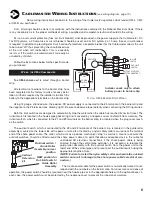
In all electrical applications, minimizing the entrance
or accumulation of moisture or water is of prime impor-
tance. Junction boxes, receptacles, breakers and other
enclosures in which electrical connections are made
should be waterproof or be installed in a protected area.
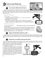
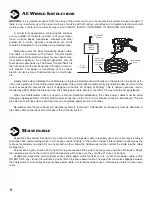
Electricity enters the boat through the power cable.
The cable is connected to the Power Transfer Switch
which automatically switches power for your boat’s elec-
trical system between the on-board generator and the
shore power cable hook up. The Power Transfer Switch is
then connected to the AC panel board through a main cir-
cuit breaker. The power is transferred to the various
branch circuits by way of individual branch circuit break-
ers.
Good practice when installing the
Cablemaster
is to place a waterproof circuit breaker in the system on the boat’s exte-
rior in close proximity to the
Cablemaster
hawse pipe. This circuit breaker automatically interrupts the flow of current if the
current exceeds the amount the circuit is designed to handle (ie: 30amp or 50amp). This is common practice recom-
mended by ABYC where the distance from the shore power cable inlet is more than 10’ away from the AC panelboard.
When two
Cablemaster
units are used on port and starboard installations, the shore power cables must be wired
through an approved rotary transfer switch before connection to the main circuit breaker on the AC panelboard. This will
provide a safe interlock when switching from one shoreside power source to another.
Remember also that your boat’s AC electrical system is “polarized.” Polarization of conductors must be observed in
the shore cable connections and throughout the entire AC system.
G
9
TO EXTEND CABLE
1)
Flip the power switch to
OUT
position; grasp the power
cord plug.
2)
Walk to dock power source and plug power cord into
recepticle.
3)
Cablemaster
will automatically shut itself OFF when
cable has fully extended. If less cable is more desire-
able, turn switch OFF and place in the
IN
position.
4)
Turn power switch OFF when desired cable length is
acheived.
TO RETRACT CABLE
1)
Disconnect the power cord plug from the dock power
source.
2)
While holding power plug, walk to
Cablemaster
.
3)
Flip the power switch to the
IN
position.
4)
Cablemaster
will automatically shut itself OFF when
cable has fully retracted.
** Do not move vessel until cable is fully retracted!
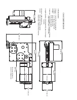
C
ABLEMASTER
O
PERATING
I
NSTRUCTIONS FOR
CM-4, CM-7, CM-8
MODELS
:
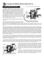
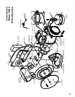
I
Power
Transfer
Swtich
Cable exits
from bottom
of storage
container
From
Generator
To Boat AC
System
T
ROUBLE
S
HOOTING
G
UIDE
J
COMPLAINT
Non-functional
(either no power or
unit has power and
does not respond)
• Tripped breaker
• Power wire incorrectly connect-
ed to relay assembly
• Defective motor
• Defective relay box
• Reset breaker
• Replace relay assembly
• With power switch on and voltage across motor wires
— if no response, replace motor
Retracts cable only
• Out-Limit switch circuit open
• Defective relay
• Bad power switch
• Check out-limit switch
• Replace relay assembly
• Check power switch
Tripped DC breaker
• Main pulley too tight
• Cable jammed and kinking
• Defective motor
• Adjust pulley
• Check for adequate storage space and/or cable for
undue kinking — see Cable Adjustment (pg. ?)
• Disconnect motor wires from relay box. Apply power
directly to motor wires; motor should run one direction or
other — no response from motor; replace motor
Pays out cable only
• In-Limit switch circuit open
• Power inputs reversed
• Defective relay or diode
• Bad power switch
• Check in-limit switch
• Check polarity on DC input wires
• Replace relay assembly
• Check power switch
PROBABLE CAUSE
RECOMMENDED ACTION
Cable storage
area


