P
OWER
C
ABLE
I
NSTALLATION
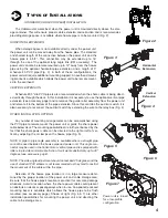
Before installing the power cable into the
Cablemaster
, stretch the cable out in a straight line on a smooth surface to
remove any kinks or unnatural coils. Feed the “blunt cut” end of the cable into the power unit. Retract the power cable,
using the power switch or manually. Before connecting the power cable to boat’s AC electrical system, secure the nylon
safety collar and refer to the Cable Adjustment section below to pre-adjust the pulley to the proper cable size and to insure
trouble-free operation of your
Cablemaster
. The power cable should be firmly strapped down, using metal or heavy duty
plastic wiring straps, to the bottom of the cable storage area so that in no way will the
Cablemaster
pull on the power
cable’s electrical connection.
In actual usage of your
Cablemaster
, you will find
that the power cable is seldom payed out completely.
Because of this, it is advisable to occasionally pay out
the cable completely and allow the cable to recoil into its
natural coil.
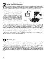
The power cable must be connected to your boat’s
AC electrical system in accordance with the instructions
contained in the National Electrical Code. Care should
be taken when adjusting the out-limit collar to ensure
that no strain will be placed upon the power cable con-
nection to the electrical system.
E
C
ABLE
A
DJUSTMENT
Shore power cable diameters vary from one cable manufacturer
to another, the
Cablemaster’s
main pulley is split in half and proper
friction adjustment between the cable and main pulley is necessary
at the time of installation. Too tight adjustment will overload the
motor. On the other hand, too loose an adjustment will result in slip-
page of the cable or no movement of the cable.
The
Cablemaster
should be able to pay in and out the cable
without any slippage or any undue strain depending on the installa-
tion, and distance from the Hawse Pipe to the Cablemaster. Some
assistance will be required when extending power cord on long
extension runs or multiple bend installations. Retracting the power
cord should not be any problem.
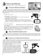
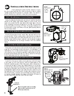
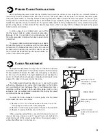
To adjust the friction between the main pulley and the power
cable follow the instructions below:
1) Remove the 1/4” nuts and lockwashers from the face of the
main pulley and remove the outer pulley half.
2) Remove or add* only equal amounts of spacers for each bolt.
3) Replace the pulley half and secure the nuts.
*When adjusting pulley friction, only add (decreases tension) or
remove (increases tension) one (1) spacer from each bolt before
checking the unit for the correct pulley friction. One spacer makes a
substantial difference in cable tension.
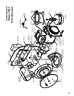
F
Remove 4 nuts &
lockwashers on face
of Main pulley
SIDE VIEW
REAR VIEW
Remove outer half of
Main pulley
Add or remove
spacers from each (4)
bolts
8
11
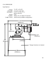
SPECIFIC
AT
IONS
Vo
ltage:
12v DC (24/32v DC a
va
ilable)
C
ur
re
n
t:
7-9
A
mps
under load
W
ei
gh
t:
21
lbs
. (p
o
we
r unit)
8
lbs
. (ha
w
se
pip
e)
Ca
b
le
siz
e:
6/4,
50
amp
, 220 v
A
djustable
(7/8”
-
1-1/4”
dia.)
Le
n
gth
c
apacit
y: D
et
er
mined
b
y siz
e
of st
or
age
lo
cat
ion
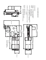
CM-7
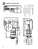
DIMENSIONS
5
"
5"
(127 mm)
Ha
w
se P
ip
e
Fl
ange
D
im.
5"
x 6 1
/2"
3 1/2"
(89
mm)
4
3/4"
(121
mm)
9 3/4"
(248 mm)
15 3/4"
(400 mm)
6 1/4"
(159 mm)
3"
(76 mm)
3 3/4"
(95 mm)
4 1/4"
(108 mm)
8 1/8"
(206 mm)
6 3/4"
M
in
(171
mm)
13" M
in.
(330 mm)
6
1/2"
(165
mm)
12 1/4"
(311 mm)
C
ABLEMASTER
D
IMENSIONS
K

