


2
G
ETTING TO
K
NOW
Y
OUR
C
ABLEMASTER
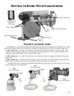
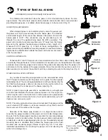
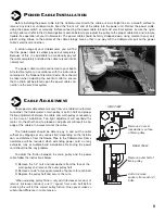
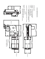
Guide Roller Assembly
Chrome Hawse Pipe
Hawse Pipe Clamp
In-Limit
Switch
Relay Assembly
(on CM-7 &
CM-8 only)
Tension Rollers
Out-Limit
Switch
Main Pulley
CM-4
(for 30 amp cable)
17
3
MODELS TO CHOOSE FROM
:
Motor
All
Cablemaster
s are designed to eliminate the physically demanding task of paying out and coiling up your shore
power cable. Powered extension and retraction is available at the flip of a switch! There are 3 models to choose from:
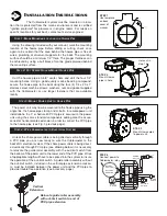
1)
CM-4 Cablemaster
— the CM-4 was designed to handle 30 amp shore power cable. The CM-4 usually comes
attached to it’s own storage container to make installation as easy as possible. You may also order the CM-4 with TV
/ telephone cable installed instead of 30 amp shore power cable.
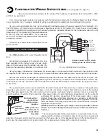
2)
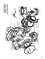
CM-7 Cablemaster
— the CM-7 (the workhorse of the
Cablemaster
line) was designed to handle 50 amp shore
power cable.
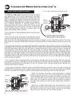
3)
CM-8 Cablemaster
— the CM-8 is our “heavy duty” version of the CM-7. The CM-8 will handle 100 amp shore
power cable. You definitely don’t want to be extending and retracting this heavy cable by hand!
All of these units can be configured to your boat’s specifications by utilizing the many accessories which aid in instal-
lation and operation of the
Cablemaster
.
CM-8
(for 100 amp cable)
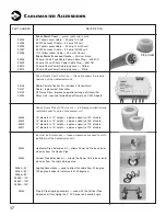
C
ABLEMASTER
A
CCESSORIES
M
PART NUMBER
94004
94008
94005
94007
94006
99408
99409
99410
99415
DESCRIPTION
S
HORE
P
OWER
C
ABLE
—
power cable sold in bulk.
6/3 Yellow Jacket Cable — 50 amp 125 volt
6/3 White Jacket Cable — 50 amp 125 volt
6/4 Yellow Jacket Cable — 50 amp 125/250 volt
6/4 White Jacket Cable — 50 amp 125/250 volt
10/3 Yellow Jacket Cable — 30 amp 125 volt
S
HORE
P
OWER
P
LUGS AND
C
OVERS
—
Marinco brand
50 amp 125/250 volt Shore Power Cable Plug — 6365CR
50 amp 125 volt Shore Power Cable Plug — 6361CR
50 amp Shore Power Cable plug cover — Yellow
50 amp Shore Power Cable plug cover — White
04146
04147
04153
04034
R
ADIO
R
EMOTE
C
ONTROL
O
PTION
—
this option allows the remote
operation of the Cablemaster unit.
Radio Remote Control Kit - includes 2 transmitters!
Spare / replacement transmitter
RF Noise Filter - improves operational range of transmitter
Relay Unit - required for addition of Remote on CM-4 models
85448
85424
85420
85421
P
OWER
C
ABLE
S
TORAGE
C
ONTAINERS
—
rotationally molded styrene
containers used to store shore power cord.
16” diameter x 13” height — approx. capacity of 40’ of cable
18” diameter x 18” height — approx. capacity of 55’ of cable
20” diameter x 18” height — approx. capacity of 75’ of cable
22” diameter x 15” height — approx. capacity of 75’ of cable
04043
04044
04062—30º
04064—60º
04066—90º
04063—120º
04067—150º
04065—180º
04045
I
NSTALLATION
A
CCESSORIES
—
these accessories are used to aid in
installation of the Cablemaster unit.
Horizontal Pipe Extension kit — allows Power Unit to be extend-
ed away from the Hawse Pipe
Vertical Pipe Extension kit — allows the Power Unit to be extend-
ed away from the cable storage area
Angling Assemblies — used to direct the cable from 30 degree -
180 degree bends (in increments of 30 degrees)
Pipe tp Pipe Angling Assembly — used with the Vertical Pipe
Extension kit for angling the 3” PVC pipe to a desired angle
Stop Collar
(CONTAINER
OPTIONAL)
CM-7
(for 50 amp cable)


