background image

Page 18

Page 19

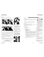
Gravity Flow Solid Fuel Boiler Pipe Layout

Min. 250mm 

Normally open

2 port valve

Pipe

stat 1

Overheat

stat 3

(

82°C)

Solid

fuel

vent

Feed and expansion tank sized to include

the expansion of solid fuel boiler, open vented

boiler and open vented central heating

This circuit usually uses gravity circulation.

Good circulation depends on the system height and the

temperature difference between the hot flow and the cool

return to provide the motive force to overcome the frictional

resistance in pipe and fittings and provide circulation.

Normally closed

2 port valve

Heat sink radiator

(ensure lockshields

are left fully open)

Multi-fuel stove

Control

stat 2

(

30°C-90°C)

Normally open

2 port valve

Solid Fuel Option

All models of the Torrent Stainless shown in this installation manual have the tappings 

included as standard for a solid fuel boiler. In the absence of recommendations from 

HETAS or the solid fuel boiler manufacturer, we would advise the following pipe layout 

to achieve the best performance from your solid fuel system and our thermal store.

This diagram represents a good example of a gravity circulation pipe layout. Points 

to note are;

•  All pipework rises towards the cylinder and the heat sink radiator and fall back 

towards the solid fuel burner.

•  The heat source is below the cylinder which gives the layout a good system height.

•  All gravity circulation pipework is recommended to be 28mm or above pipe 

diameter, at low flow speeds the pipe resistence is negligible in this pipe diameter.

•  Avoid long horizontal runs and try to make the ratio horizontal:vertical to be a 

maximum of 20:80.

To ensure that the solid fuel boiler does not overheat the thermal store during its 

operation and prevent gravity circulation cooling the thermal store when it is not, 

the following controls can be used. Other methods of control can be used; HETAS 

and/or the solid fuel boiler manufacturers instructions should be consulted. This 

control system is fed from a dedicated fuse spur to enable safe isolation for changing 

components. All wiring should comply with BS7671 Requirements for Electrical 

Installations latest edition.

Typical components (not supplied but available to purchase from Gledhill Spares Ltd);

•  Honeywell V4043B1265 (XB165) - 28mm compression normally open 2 port valve

•  Honeywell V4043H1106 (XC012) - 28mm compression normally closed 2 port valve

•  Honeywell L641B1012 (XC016) - Pipe thermostat

•  (XC010) - Control thermostat 2

•  (XC011) - Overheat thermostat 3

INSTALLATION

INSTALLATION

TORRENT STAINLESS SP SOL

SOLID FUEL BOILERS

When the boiler is lit, the water temperature 

raises. When the temperature is above pipe 

thermostat 1 set point, the contacts close 

signalling the normally closed valve to move 

open. Once it is fully open, it signals the 

normally open valve to motor there by closing 

it. The thermal store now receives heat from the 

solid fuel boiler via gravity circulation.

If control stat 2 set point is exceeded then the 

power to the normally closed valve is cut which 

in turn cuts the power to the normally open 

valve. Excess heat from the solid fuel boiler is 

then circulated around the heat sink radiator. 

Careful selection of the pipe and control 

thermostat set points should be made during 

commissioning to get the best performance 

from the system. 

Setting control stat 2 at too high temperature 

will cause dripping at overheat stat 3. We 

recommend that there is a gap of at least 7°C 

between the two stats. Therefore 75°C is ideal.

If temperatures in store exceed 82°C the 

secondary protection will cut off the power 

(overheat stat 3) in accordance with Part G3 of 

Building regulations.

With regards to the domestic hot water 

overheat protection, please refer to page 17 in 

this installation manual.

Feed and Expansion Tank

A feed and expansion cistern supplying a system 

heated by wet solid fuel appliance should either 

be of metal construction (copper, stainless 

steel etc.) or manufactured of a material 

that has been certified as being suitable for 

temperatures up to 110

°

C. These are available 

to order from Gledhill at the time of purchase.

The capacity of the cistern should be at least 

one twentieth of the total system volume.

The cistern should be fitted with a brass float 

operated valve that is manufactured to BS1212 

Pt. 2 and is fitted with an appropriately sized 

copper float. The overflow pipe should be either 

made of metal or manufactured from a material 

that has been certified as being suitable for 

temperatures up to 110

°

C. The overflow pipe 

must have appropriate support – for plastics 

this may require continuous support. 

Torrent Stainless SP SOL boiler only

Where the Torrent Stainless SP SOL product is 

selected to be used purely with a sealed primary 

boiler, by combining the boiler and solar coils 

the volume of heated water will increase.

The diagrams opposite show the pipe 

configurations recommended to maximise 

the boilers input where the two coils are utilised.

The 150 litre model internal coils can be 

connected in series, with the SP boiler return 

connected to the solar flow.

We recommend the 180 to 350 litre models 

are connected in parallel to maximise the heat 

transfer into the cylinder.

Coil Connection With Boiler Input Only (150 litre models)

Sealed
system

kit

Central Heating Return

Central Heating Flow

Coil Connection With Boiler Input Only (180-350 litre models)

Central Heating Return

Central Heating Flow

Sealed
system

kit

Summary of Contents for Torrent Stainless OV

Page 1: ...WWW GLEDHILL NET ONE NAME EVERY SOLUTION TORRENT STAINLESS OPEN VENTED STAINLESS STEEL THERMAL STORE PROVIDING HEATING AND MAINS PRESSURE HOT WATER INSTRUCTION MANUAL DESIGN INSTALLATION SERVICING ...

Page 2: ...0Vac 50Hz TheTorrent Stainless comes complete with plate heat exchanger This has a very small volume of water held within it therefore any minimal expansion will be accomodated in the supply pipe Handling Before Installation The Torrent Stainless must be handled with care and stored the correct way up in a dry place Any manual handling lifting operations will need to comply with the requirements o...

Page 3: ...7 220 838 430 804 504 1365 n a 0 78 178 73 8 26 5 TST210OVSOL B 62 198 42 250 1494 550 285 n a n a 515 235 1015 537 220 1015 540 1071 611 1553 n a 1 27 208 83 7 26 5 TST250OVSOL C 74 236 47 295 1744 550 285 n a n a 515 235 1040 537 220 1040 540 1441 761 1803 n a 1 27 248 96 9 26 5 TST350OVSOL C 79 328 57 402 1765 630 285 n a n a 498 218 971 520 218 971 523 1446 676 1826 n a 1 27 345 129 9 26 5 Tor...

Page 4: ...d Fuel ControlThermostat 22mm Dual Pocket 22 Hot water supply 22mm Compression 23 Mains cold water supply 22mm Comp Torrent Stainless SP SOL Available Components and Tappings 1 Open Vent 22mm Compression 2 Cold Feed F E tank 22mm Compression 3 Immersion Heater 1 3 4 Female 4 Solar Coil Flow 22mm Compression 5 Solar Coil Return 22mm Compression 6 Control Thermostat Pocket 22mm Dual Pocket 7 Control...

Page 5: ...available when the local demand is at its maximum but the preferred range is between 2 and 3 0 bar If the incoming static mains pressure exceeds 5 0 bar at any point in the 24 hour cycle then a pressure limiting valve set at 3 0 bar should be fitted downstream of the stop tap where the cold supply enters the dwelling If a water meter is fitted in the service pipe it should have nominal rating to m...

Page 6: ...d by the installer must be sized correctly to enabletheexpansionoftheentiresystemvolume Thiswillincludethecentralheating store solid fuel and boiler circuit volumes See page 12 for guidance sizing the feed and expansion tank Water Treatment In all Torrent Stainless models the primary i e non potable water is stored and the domestichotwaterisheatedinstantaneouslybymeansofheatexchangers Therefore tr...

Page 7: ...thiscasenobypassvalve is required unlessTRV s are used on all radiators If the flow and return pipes between the boiler and the Torrent Stainless OV thermal store are dipped as illustrated in the schematic shown opposite then the boiler selected must be suitableforasealedheatingsystemi e itmustbe fitted with an overheat thermostat Automatic air vents should be fitted at appropriate places to vent ...

Page 8: ... Stainless SP please refer to page 19 for further information Where a sealed primary coil is used the thermal store is a hot water only thermal store If too much heat is taken out of store then hot water performancewillbelimited Thehotwaterpriority should be protected by use of an appropriate thermostat Heating can be taken from the SP thermal store to provide auxilliary heating to towel radiators...

Page 9: ... the store to provide shower or a bath to utilise the heat gained by the system from the previous day s solar energy input Alternatively showering or bathing in the evening will utilise the energy that has been stored during the day from the solar system Aswithanysystem hotwaterandspaceheatingshouldbeprogrammedaccording to house holder requirements However it is always good to remember that to gai...

Page 10: ...re raises When the temperature is above pipe thermostat 1 set point the contacts close signalling the normally closed valve to move open Once it is fully open it signals the normally open valve to motor there by closing it The thermal store now receives heat from the solid fuel boiler via gravity circulation If control stat 2 set point is exceeded then the power to the normally closed valve is cut...

Page 11: ...2 c c 230Vac 50HZ Mans supply L N Bottom store thermostat Top store Thermostat 2 Pole CO relay 230Vav coil NC NO NC NO L N Heat source Control supply C Common contact C Common C 1 Close on temperature rise NO normally open C 2 Close on temperature drop NC normally closed Figure 8 1 Example of twin thermostat control circuit wiring for thermal stores WA Specification for thermal stores 2010 Final v...

Page 12: ...sensors S1 and S2 In this case the mechanical overheat thermostat S3 shown in this diagram is not required and the solar pump is wired straight to the solar controller NOTE As part of system setup and commissioning it is important that this boiler hold off pipe thermostat be adjusted to find the best setting for each individual installation Failure to do so will give under performance of either th...

Page 13: ...which is wired directly to the solar controller same as sensors S1 and S2 In this case the mechanical overheat thermostat S3 shown in this diagram is not required and the solar pump is wired straight to the solar controller Normally Closed 2 Port Valve E N SL PL ML Pipe Thermostat 1 1 C 2 on off NOTE As part of system setup and commissioning it is important that this boiler hold off pipe thermosta...

Page 14: ...rom over heating by stopping the solar Pump at pre set temperature limit S1 S2 S3 E N R1 N R1 N L 1 2 3 4 5 6 7 8 12 13 14 15 16 17 18 19 20 Solar controller N L E 1 2 3 Normally Closed 2 Port Valve E N SL PL ML Pipe Thermostat 1 1 C 2 on off NOTE As part of system setup and commissioning it is important that this boiler hold off pipe thermostat be adjusted to find the best setting for each indivi...

Page 15: ...t the hot tap does not indicate that the TorrentStainlessisfull Checkthatthereiswaterinthefeedandexpansiontankbefore switching on the immersion heaters Dry firing the elements will cause premature failure which is not covered by our warranty Non Electric Torrent Stainless Models Opentheincomingstopvalveandfillthedomestichotwatersystem Foropenvented heating system fill the whole of the primary heat...

Page 16: ...ling prior to switching the electricity supply to the PWM controller PCB If there is no water in these pipes then there may be significant wear on the PWM pump This can be confirmed by Checking the thermal store pipework servicing valves are open Looseningtheconnectionpointsonthethermalstorepipeworkinasystematic manner and checking for water presence Confirming that the feed and expansion tank has...

Page 17: ...tion in this procedure is that the plumbing and water supply is working effectively If in doubt please confirm and refer to the end of this section for advice on specific components A multi meter a weir gauge and a thermometer will be required to confirm that all the components are working effectively The PWM controller PCB manufacturer suggests Fluke 87 TRUE RMS Multi meter as a suitable product ...

Page 18: ...on Sensor required a power supply 5 VDC Open a HW tap and set to a flow rate Measure and record the frequency across terminals 1 and 12 Compare the frequency measured with chart flow rate determination The reading should make sense taking measurement conditions into consideration 1 2 3 4 5 6 7 8 9 10 11 12 13 14 1 2 3 4 1 2 3 4 1 2 3 4 5 6 7 8 1 2 1 2 3 4 5 6 7 8 9 1 10 2 3 4 5 6 J18 J20 J19 J3 J7...

Page 19: ...lure Pump restarts by itself after the fault has disappeared Under voltage U 160 V or Over voltage U 253 V Check voltage supply 195 V U 253 V Pump overheating temperature inside motor too high Check water and ambient temperature Over speed the pump rotor is driven by an external flow above the maximum allowed value Ensure that there is no other external flow other pump running on system Over curre...

Page 20: ...upply Electrically safe Components short circuited Wiring as per circuit diagram Pump LED on N Check cable connec on secure and resistance in cable Pump running LED is damaged pump replacement op onal OK Y Resolve N Electronics damaged replace pump LED Blinks red Y Y Check for blockage in pipework or pump housing N LED con nues to Blink red a er power reset Y Motor or Electronics damaged replace p...

Page 21: ...asier and should be in good health Persons below average build and strength may require more rest periods during the handling process Pregnant women should not carry out this operation Persons who are not in good health should seek medical advice prior to commencing any lifting or manual handling operation Residual risk Following the guidelines given above will reduce any risk to injury All person...

Page 22: ...Page 42 Page 43 NOTES NOTES ...

Page 23: ...se which are contained on the Invoice Forms and all Sales are now subject to these Conditions of Sale and Warranty terms only 2 PRICE Once an order or call off has been accepted the price will be held for three months but if delivery is extended beyond that period at the customer s request then we reserve the right to amend the price when necessary The company reviews its pricing annually to adjus...

Page 24: ...o Comments Signature SERVICE 07 Date Engineer name Company name Telephone No Comments Signature SERVICE 09 Date Engineer name Company name Telephone No Comments Signature SERVICE 02 Date Engineer name Company name Telephone No Comments Signature SERVICE 04 Date Engineer name Company name Telephone No Comments Signature SERVICE 06 Date Engineer name Company name Telephone No Comments Signature SERV...

Page 25: ...3 474412 OR WWW GLEDHILL SPARES NET Due to a programme of continuous improvement Gledhill Building Products reserve the right to modify products without prior notice It is advisable to check the product technical detail by using the latest design and installation manuals available from our technical support team or on our website It is an offence to copy or adapt this document without consent of t...

Reviews: