ITEM 15
C.
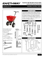
Slide Inner Axle Bush (ITEM 12 - 2 off) over each end of the Gearbox and Axle Assembly
(ITEM 2) and fully insert into the Axle Bush (ITEM 5 - 2 off).
Locate Wheel (ITEM 13) onto the right hand Axle and align the hole in the wheel hub
with the hole in the axle. Insert M5 x 45mm Bolt (ITEM 14) and M5 Lock Nut (ITEM 15) to
secure the Drive Wheel. Gently tap the Axle End Cap (ITEM 16) into position.
Locate the 4 x Wheel Washers (ITEM 33’s) onto the left hand Axle followed by the Free
Wheel (ITEM 13) and 16mm Flat Washer (ITEM 17). Tap the Axle End Cap in position to
secure the Wheel.
ITEM 12
ITEM 13
ITEM 14
ITEM 16
ITEM 17
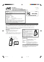
D.
Insert the Handle Shaft (ITEM 18) between
the two Wheel Assembly Frames (ITEM 4)
ensuring the Handle Shaft is in the correct
orientation. The lower holes are further
from the end of the Handle Shaft.
Take the Pivot Bracket Assembly (ITEM
19) and align with the holes in the Wheel
Assembly Frames and Handle Shaft.
Secure in position using M6 x 55mm Bolt
(ITEM 11 - 2 off) and M6 Lock Nut (ITEM 9).
FULLY TIGHTEN ALL NUTS AND BOLTS
WITHIN THE ASSEMBLY FROM STEP A
- DO NOT OVER TIGHTEN -
ITEM 18
ITEM 4
ITEM 19
ITEM 9
ITEM 11
ITEM 33 (x 4)