


36
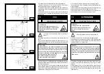
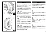
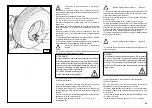
MONTAGGIO CON UTENSILE A BECCO
1) Procedere come descritto ai punti 1,2,3,4,5 del montaggio con
disco stallonatore.
2) Portare il braccio portautensili in posizione di fuori lavoro; traslarlo
sul fianco interno del pneumatico e riagganciarlo in questa posizione.
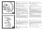
3) Verificare che l'utensile a becco sia posizionato sul lato della
ruota. In caso contrario premere la leva (15, Fig. D) e ruotare di
180°.
MOUNTING WITH THE HOOKED TOOL
1) Follow the steps described in points 1,2,3,4,5 for mounting with
the disk.
2) Move the tool carrier arm to its non-working position. Move it to the
inside plane of the tyre and rehook it at this position.
3) Check to make sure the hook tool is positioned on the wheel
side. If not, press lever (15, Fig. D) and turn it 180°.
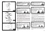
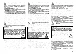
Take the mobile control unit to work position D.
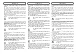
4) Move the tool forward until the red reference dot is lined up with
the outside edge of the rim and about 5 mm from it (See Fig. O).
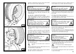
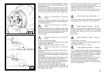
4) Avanzare con l'utensile fino a portare il suo punto rosso di riferi-
mento in asse con il bordo esterno del cerchio ad una distanza di 5
mm. dallo stesso (vedi Fig. O).
Portarsi con la colonnetta mobile in posizione di
lavoro D.
Portarsi con la colonnetta mobile in posizione di
lavoro C.
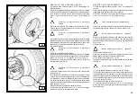
5) Move to the outside of the wheel and check the exact position
of the took visually and adjust it as needed. Then turn the spindle
clockwise until the clip is at the bottom (6 o’clock). The first bead will
be on the rim.
6) Remove the clip.
5) Portandosi sull'esterno della ruota controllare visivamente l'esatta
posizione dell'utensile ed eventualmente correggerla, quindi ruotare
l'autocentrante in senso orario fino a portare la pinza nel punto più in
basso (ore 6). Il primo tallone risulterà inserito nel cerchio.
6) Rimuovere la pinza.
7) Fare uscire l'utensile dal pneumatico.
8) Portare il braccio portautensili in posizione di fuori lavoro; traslarlo
sul fianco esterno del pneumatico e riagganciarlo in questa posizione.
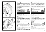
9) Ruotare l'utensile di 180° agendo sulla leva (15, Fig. D).
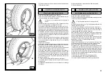
10) Montare la pinza nel punto più in basso (ore 6) al di fuori del
secondo tallone (vedi Fig. N).
Portarsi con la colonnetta mobile in posizione di
lavoro D.
11) Ruotare l'autocentrante in senso orario di circa 90° (fino a portare
la pinza a ore 9).
12) Avanzare con l'utensile fino a portare il suo punto rosso di riferi-
mento in asse con il bordo esterno del cerchio ad una distanza di 5
mm. dallo stesso. Iniziare la rotazione in senso orario controllando
che, dopo una rotazione di circa 90°, il secondo tallone abbia iniziato
a scivolare nel canale del cerchio. Ruotare fino a portare la pinza nel
punto più in basso (ore 6).
Anche il secondo tallone risulterà inserito nel cerchio.
13) Procedere come descritto ai punti 11, 12, 13, 14, 15 del montaggio
con disco per rimuovere correttamente la ruota.
Take the mobile control unit to work
position D.
7) Remove the tool from the tyre.
8) Move the tool carrier arm to its non-working position. Move it to the
outside plane of the tyre and rehook it in this position.
9) Turn the tool 180° with lever (15, Fig. D).
10) Attach the clip at the bottom (6 o’clock) outside the second bead
(See Fig. N).
Take the mobile control unit to work
position C.
11) Turn the spindle clockwise to about 90° (clip at 9 o’clock).
12) Bring the tool forward until the red reference dot is lined up with
the outside edge of the rim and about 5 mm from it. Begin to turn the
spindle clockwise and check if, after about 90° of rotation the second
bead has started to slip into the centre well. Continue turning until the
clip is at the bottom (6 o’clock).
The second bead will now be mounted on the rim.
13) Follow the steps described in points 11, 12, 13, 14, 15 for mounting
with the disk since this will ensure that the wheel is removed correctly
from the machine.
O
N
Portarsi con la colonnetta mobile in posizione di
lavoro C.
Take the mobile control unit to work
position C.
Summary of Contents for S 551 XL A
Page 65: ...65 230 V 1 ph...
Page 66: ...66 220 V 3 ph...
Page 67: ...67 400 V 3 ph...
Page 68: ...68 SCHEMA ELETTRICO ELECTRIC DIAGRAM SCHEMA ELECTRIQUE SCHALTPLAN ESQUEMA ELECTRICO 2...
Page 72: ......


