


9
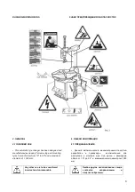
• It is forbidden to use the machine for straightening rims,
breaking beads of still inflated or dirty tyres, removing
bead wires.
• In particular THE MANUFACTURER cannot be held
responsible for any damage caused through the use of
this tyre changer for purposes other than those specified
in this manual, and therefore inappropriate, incorrect and
unreasonable.
•
Запрещается
эксплуатация
шиномонтажного
стенда
для
:
выправления
дисков
,
отжима
борта
накаченных
или
грязных
шин
,
удаления
бортовой
проволоки
шин
.
•
ПРОИЗВОДИТЕЛЬ
не
несет
ответственности
за
повреждения
,
вызванные
использованием
данного
шиномонтажного
стенда
для
других
целей
,
не
указанных
в
данном
руководстве
и
которые
,
в
связи
с
этим
,
являются
несоответствующими
,
неправильными
и
нецелесообразными
.
2.2 GENERAL SAFETY PRECAUTIONS
The tyre changer may only be used by
specially trained and authorized
expert personnel.
• Any tampering or modification to the equipment
carried out without the manufacturer’s prior
authorization will free him from
all
responsibility for damage caused directly or
indirectly by the above actions.
• Removing or tampering with safety devices
immediately invalidates the guarantee and is in
contravention of European Safety Standards.
• The tyre changer comes complete with instruction
and warning transfers which are designed to be
long-lasting.
If they should for any reason be damaged or
destroyed, please ask immediately for replacements
from the manufacturer
using the codes given
on page 8.
2.2
ОСНОВНЫЕ
ПРАВИЛА
БЕЗОПАСНОСТИ
•
Любое
вмешательство
или
изменение
конструкции
оборудования
,
проведенные
без
предварительного
разрешения
производителя
,
освобождают
его
от
ответственности
за
повреждения
,
вызванные
напрямую
или
косвенно
вышеупомянутыми
действиями
.
•
Снятие
или
несанкционированное
вмешательство
в
работу
защитных
устройств
моментально
аннулирует
гарантию
и
противоречит
Европейским
Стандартам
Безопасности
.
•
Шиномонтажный
стенд
укомплектован
переводными
наклейками
с
инструкциями
и
с
предупреждениями
,
которые
рассчитаны
на
длительный
срок
службы
.
Если
они
по
какой
-
либо
причине
будут
повреждены
,
необходимо
немедленно
запросить
у
производителя
замену
,
используя
коды
,
указанные
на
стр
. 8.
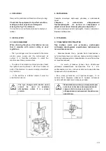
3. TRANSPORT
• The tyre changer must be transported in its original
packaging and kept in the position shown on the
package itself.
• The packaged machine may be moved by means of a
fork lift truck of suitable capacity. Insert the forks at the
points shown in figure 3.
3.
ТРАНСПОРТИРОВКА
•
Шиномонтажный
стенд
должен
транспортироваться
в
оригинальной
упаковке
и
находиться
в
положении
,
указанном
на
упаковке
.
•
Упакованный
стенд
может
быть
перемещен
с
помощью
вильчатого
погрузчика
соответствующей
грузоподъемности
.
Вставляйте
вилы
в
места
,
показанные
на
Рис
. 3.
Шиномонтажный
стенд
может
использоваться
только
специально
обученным
и
уполномоченным
квалифицированным
персоналом
.
Summary of Contents for 0202380
Page 1: ...1 AUTOMATIC TYRE CHANGER INSTALATION OPERATION AND MAINTENANCE GUIDE...
Page 29: ...29 14 ELECTR AND PNEUM DIAGRAMS 14...
Page 30: ...30...
Page 31: ...31...
Page 33: ...33...


