GIULIANO 0202380 Installation, Operation & Maintenance Manual Download Page 17


17 

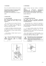
•    Position  the  wheel  against  the  rubber  stops  on  the 

right side of the tyre changer (S). 

 
•    Position  the  bead  breaker blade  (R)  against  the  tyre 
bead at a distance of about 1 cm from the rim (fig.15). 
Pay attention to the blade, which must operate correctly 
onto the tyre and not onto the rim. 
 
•    Press  down  the  pedal  (U)  to  activate  the  bead 
breaker and release it when the blade has reached the 
end  of  its  travel  or  in  any  case  when  the  bead  is 
broken. 
 
•  Rotate the tyre slightly and repeat the operation 
around the entire circumference of the rim and from 
both sides until the  bead is completely detached from 
the rim. 

• 

Поместите


колесо


на


резиновый


упор

расположенный


на


правой


стороне


шиномонтажного


стенда

 (S). 

 
• 

Приблизьте


лопатку


устройства


отжима


борта

  (R) 

к


борту


шины

сохраняя


дистанцию


приблизительно


в

 1 

см


от


диска

  (

Рис

.  15). 

Уделяйте


внимание


положению


лопатки

которая


должна


действовать


на


шину

а


не


на


диск

.


• 

Нажмите


на


педаль

  (U) 

для


того

чтобы


включить


устройство


отжима


борта

Отпустите


ее

когда


лопатка


достигнет


конца


своего


движения


или

пока


шина


не


будет


полностью


отделена


от


обода


колеса

 
•   

Слегка


проворачивайте


шину


и


повторяйте


операцию


по


всей


окружности


обода


и


с


обеих


сторон


шины


до


тех


пор

пока


борт


не


будет


полностью


отделен


от


обода


6.2 REMOVING THE TYRE 


Before  any  operation  remove  the  old 
wheel balancing weights and check that 
the tyre is deflated. 


During arm tilting make sure that 
nobody stays behind the tyre-changer. 


•    Press  pedal  (H)  to  tilt  the  arm  (P)  thereby  clearing  the 
turntable. 
•  Spread the supplied grease (or grease of a similar type) onto 
the tyre bead. 


Failure to use the grease supplied risks 
causing serious damage to the tyre 
bead. 


6.2 

ДЕМОНТАЖ


ШИНЫ


Перед


какими

-

либо


операциями


удалите


все


старые


балансировочные


грузы


колеса


и


убедитесь


в


том

что


из


шины


выпущен


воздух


Во


время


наклона


монтажной


стойки


убедитесь

что


никто


не


находится


позади


шиномонтажного


стенда


• 

Нажмите


педаль

  (

Н

для


того

чтобы


наклонить


монтажную


стойку

 (P) 

и


этим


освободить


рабочее


пространство

• 

Нанесите


на


борт


шины


смазку

поставленную


с


устройством


(

или


смазку


подобного


типа

). 


В


случае


неиспользования


смазки

поставляемой


с


устройством

возникает


риск


серьезных


повреждений


борта


шины


Summary of Contents for 0202380

Page 1: ...1 AUTOMATIC TYRE CHANGER INSTALATION OPERATION AND MAINTENANCE GUIDE...

Page 2: ...86 217 CEE 87 404 CEE 2006 42 CE 91 368 CEE 93 68 CEE 2006 95 CE 2004 108 CE as well as to the following norms EN 12100 EN 60204 1 The signer of this declaration of conformity is the person authorized...

Page 3: ...Scrapping must be made in accordance with the following Directive 2002 96 CE and 2003 108 CE RAEE as well as with the national laws in force in the Country of Installation Correggio 07 05 2014 07 05 2...

Page 4: ...marked on the product refers to this prescription Scrapping must be made in accordance with Directives 2002 96 CE and 2003 108 CE RAEE as well as with the local Regulations in force in the Country of...

Page 5: ...5 Clamp locking value adjust 6 OPERATION 6 1 Breaking the bead 6 2 Removing the tyre 6 3 Mounting the tyre 7 INFLATING 7 1 Inflating with airline gauge optional 8 MOVING 9 STORAGE 10 SCRAPPING 11 MAIN...

Page 6: ...of your tyre changer in the box below If there is any discrepancy between the data provided in this manual and that shown on the plate fixed to the tyre changer the latter should be taken as correct...

Page 7: ...bar N Horizontal arm P Vertical arm Q Air supply R Bead breaker S Wheel support T Bead lifting lever U Bead breaker control pedal V Clamp control pedal Z Reverser control pedal with 2 speed H Tilting...

Page 8: ...This automatic tyre changer has been designed and manufactured exclusively for removing and mounting tyres from onto rims from 10 to 24 and a maximum diameter of 1000 mm Any other use is to be consid...

Page 9: ...rization will free him from all responsibility for damage caused directly or indirectly by the above actions Removing or tampering with safety devices immediately invalidates the guarantee and is in c...

Page 10: ...safety at work regulations The tyre changer must be connected to the mains electric power supply and the compressed air system It is therefore advisable to install the machine near these power sources...

Page 11: ...aking care not to tighten too much to enable cylinder to operate correctly so tilting the arm without frictions Tighten screw 8 shown in picture 8 Fix the inflating gauge hook 9 on the vertical arm Ti...

Page 12: ...manometer box to the vertical arm through the proper screws Let the connection spiral hose pass through the small hole on the back side of the machine body Connect the rilsan hose to the union of the...

Page 13: ...omatic circuit breaker differential set at 30 mA Note Should the tyre changer be lacking in electric plug so the user must set one which is at least 16 A and which conforms to the voltage of the machi...

Page 14: ...N and the horizontal arm M The mounting head positions itself automatically at the correct distance from the rim With the button in Pos 2 the arms are unlocked and the mounting head goes down onto the...

Page 15: ...inimum of 10 20 ext and 12 22 int until a maximum of 12 22 ext and 14 24 int To change the position proceed as follows Unscrew screw 1 by means of the Allen wrench Remove the locking clamp 2 and the s...

Page 16: ...r 2008632 and to limit the pressure exerted by turntable to 5 bar max in order to avoid any irreparable damage of deformation If your tyre changer is not equipped with pressure regulator it is advised...

Page 17: ...when the bead is broken Rotate the tyre slightly and repeat the operation around the entire circumference of the rim and from both sides until the bead is completely detached from the rim S R 1 15 U...

Page 18: ...ake sure that the rim is firmly fixed to the clamps Never keep your hands onto the wheel the arm recovery to working position could set the operator at risk of hand crushing between rim and mounting t...

Page 19: ...to remove the inner tube if there is one without unlocking the mounting bar tilt the arm P by pushing pedal H down Repeat the operation for the other bead I 16 10 Y Z 17 6 3 MOUNTING THE TYRE WARNING...

Page 20: ...arm recovery to working position could set the operator at risk of hand crushing between rim and mounting tool Move the tyre so that the bead passes below the front section of the mounting head and is...

Page 21: ...even death of the operator Check carefully that the wheel rim and the tyre are of the same size Check the state of wear of the tyre and that it has no defects before beginning the inflation stage Inf...

Page 22: ...lator gauge Continue to inflate the tyre with short jets of air and constantly checking the pressure between air jets until the required pressure has been reached 7 1 EXPLOSION HAZARD Never exceed 3 5...

Page 23: ...9 STORAGE In the event of storage for long periods of time be sure to Disconnect all sources of power and grease the clamp sliding guides on the turntable to prevent them from oxidising 9 10 SCRAPPING...

Page 24: ...r it is necessary to break the bead loadless 3 4 times in order to let the air in pressure go out of the circuit 11 11 1 3 4 Defective parts must be replaced exclusively by expert personnel using the...

Page 25: ...e screws on the turntable slides Fig 23 Note In the event of a loss of power check that the drive belt is tight as follows 30 F ISO HG ISO VG 32 ESSO Febis K32 Mobil Vacouline Oil 1045 KLUBER Airpress...

Page 26: ...Clean by a jet of compressed air or if damaged replace by referring to the spare parts catalogue For cleaning or replacing the silencer of bead breaker see fig 27 and proceed as shown on previous poi...

Page 27: ...linder gaskets The tool touches the rim during the tyre removing mounting operations Locking plate incorrectly adjusted or defective Adjust or replace locking plate chap 11 fig 25 Turntable locking sc...

Page 28: ...eaker blade 10 bar 30800 N 10 30800 Working pressure 10 bar 145 psi 10 145 Inflating pressure limiting device max 3 5 bar 50 psi 3 5 50 Power supply voltage 400V 3ph 400V 3ph 2 speed 220V 1ph 220V 1ph...

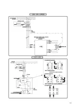
Page 29: ...29 14 ELECTR AND PNEUM DIAGRAMS 14...

Page 30: ...30...

Page 31: ...31...

Page 32: ...Turntable valve 8 Rotating union 9 Lubricator 10 Pressure regulator 11 Air intake cock 12 Safety valve 13 Pressure regulator 14 Arm tiliting valve 15 Arm tiliting cylinder 16 Arm release secure valve...

Page 33: ...33...

Reviews: