background image

40

ENGLISH

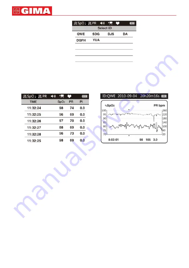
Figure 20. Select ID interface

Choose the review record and press menu button to enter the review interface. Choose “VALUE” to 

enter true value review interface as figure 21. Choose “TREND” to enter trend review interface as figure 

22.


Figure 21. VALUE review interface 

Figure 22. TREND review interface

In value review mode, press “left button” or “right button” to page up or page down, press “up button” or 

“down button” to page up or page down quickly. The displayed time on the right top is the total recording 

time. 

In trend review mode, the pink number on the left bottom is current recording time point of the trend 

graph, the middle azury font is SpO

2

 value, yellow font is pulse rate value, the green front on the right 

bottom is PI value. Press “up button” or “down button” to page up or page down; Press “left button” or 

“right button” to move the recording time which is denoted by pink triangle.

5.3.6 Close the device

A.  In the main menu interface, move the choice bar to the “Power “ item, then press menu button to 

close the device. If the record function has been opened, the prompt interface of “Recording...” will 

appear when closing the device. It means that the device is in the record state, can’t be closed.

B.  In the state of boot-strap, long press power button could close the device too.

5.4 Data upload

Please connect the device to the computer by data line, then double click “SpO

2

 Assistant” icon to run 

the PC software. The functions such as uploading real time/ memory data and change device ID could 

be carried out by the software. Please refer to <Smart Device Assistant> for detail.

Note: If the patients choose to turn on the display function on computer, it would probably take 

several seconds for the data to appear on the computer screen. (If there is no data on the com-

puter screen, unplug data line,then repeat step again.) 

Summary of Contents for OXY-200

Page 1: ...MS CO LTD No 112 Qinhuang West Street Economic Technical Development Zone 066004 Qinhuangdao Hebei Province PEOPLE S REPUBLIC OF CHINA Made in China Importato da Imported by Import par Importado por G...

Page 2: ...device or replacement of the battery non detachable lithium battery can only be performed by qualified service personnel specified by manufacturer dangers such as over temperature fire or explosion m...

Page 3: ...tic field Using the device in an inappropriate environment may cause interfer ence to the surrounding radio equipment or affect its working When storing the device keep it away from children pets and...

Page 4: ...ant physiological parameter for the respiratory and circulatory system A number of diseases related to respiratory system may cause the decrease of SpO2 in the blood furthermore some other causes such...

Page 5: ...ory result please stop using it Data averaging and signal processing generate delay on displayed and transmitted SpO2 value and alarm signal generation The data update period is shorter than 30 s the...

Page 6: ...b with the blood pressure cuff arterial ductus or intra luminal tube The measured value may be inaccurate during defibrillation and in a short period after defibrillation as it has not defibrillation...

Page 7: ...a pho tosensitive element information acquired through which will be shown on screen through treatment in electronic circuits and microprocessor 3 FUNCTIONS A SpO2 value display B Pulse rate value di...

Page 8: ...e alarm sound pause The pause time could be set by menu Long press it to confirm the alarm and there will be no alarm this time 3 Return button return to the previous menu 4 Up button down button left...

Page 9: ...the other end into computer 4 5 Structure accessories and software description A Structure main unit Oximeter probe A power supply line and A data line B Accessories one User Manual one power supply...

Page 10: ...o alarm this time 5 3 Menu operation Under the measurement interface press the menu button to enter the main menu interface as shown in Figure 5 system display clock alarm and recond etc can be set me...

Page 11: ...ss move the choice bar to the Brightness item then press left right button to set three levels B Mode move the choice bar to the Mode item then press left right button to switch display mode two kinds...

Page 12: ...e press return button to return to the main menu 5 3 4 Alarm setting When the device is turned on the red and yellow alarm lamp flash alternately once which indicates that the alarm system is working...

Page 13: ...me move the choice bar to the Alarm Volume item then press left right button to set the volume three levels d Alarm Pause sec move the choice bar to the Alarm Pause sec item then press left right to s...

Page 14: ...In Input ID interface aglimmer cursor appears in the ID input box The pink letter is the selected letter in dummy keyboard Press direction key to choose the letter to input and press menu button to i...

Page 15: ...n B Memory Manager setting In the Record menu interface move the choice bar to the Memory Manager item then press menu button to enter ID Manager interface as figure 18 Figure18 ID Manager interface I...

Page 16: ...tton or right button to move the recording time which is denoted by pink triangle 5 3 6 Close the device A In the main menu interface move the choice bar to the Power item then press menu button to cl...

Page 17: ...pls safety and monitoring performance It is recommended that the device should be inspected weekly at least When there is obvious damage stop using it B Please clean and disinfect the device before af...

Page 18: ...charged fully 2 The device works abnormally 1 Please charge the battery 2 Please contact the after sales The battery can not be full charged even after 10 hours charging time The device works abnormal...

Page 19: ...he following symbols SpO2 see note 1 Display range 0 100 Measured range 0 100 Accuracy see note 2 70 100 2 0 69 unspecified Resolution 1 PR Display range 30 bpm 250 bpm Measured range 30 bpm 250 bpm A...

Page 20: ...asurements taken over the full range By artificial inducing get the stable oxygen level to the range of 70 to 100 SpO2 compare the SpO2 values collected by the secondary standard pulse oximeter equipm...

Page 21: ...intended for use in the electromagnetic environment specified below The pur chaser or the user of the Pulse Oximeter should assure that it is used in such environment Immunity test IEC60601 test level...

Page 22: ...t 80 MHz and 800 MHz the higher frequency range applies NOTE 2 These guidelines may not apply in all situations Electromagnetic propagation is affected by absorption and reflection from structures obj...

Page 23: ...2570 Bluetooth WLAN 802 11 b g n RFID 2450 LTE Band 7 Pulse modulation b 217 Hz 2 0 3 28 5240 5 100 5 800 WLAN 802 11 a n Pulse modulation b 217 Hz 0 2 0 3 9 5500 5785 NOTE If necessary to achieve the...

Page 24: ...t in improper operation 4 Portable RF communications equipment including peripherals such as antenna cables and external antennas should be used no closer than 30 cm 12 inches to any part of the devic...

Reviews: