background image

Chapter 4  Operation 

- 18 - 


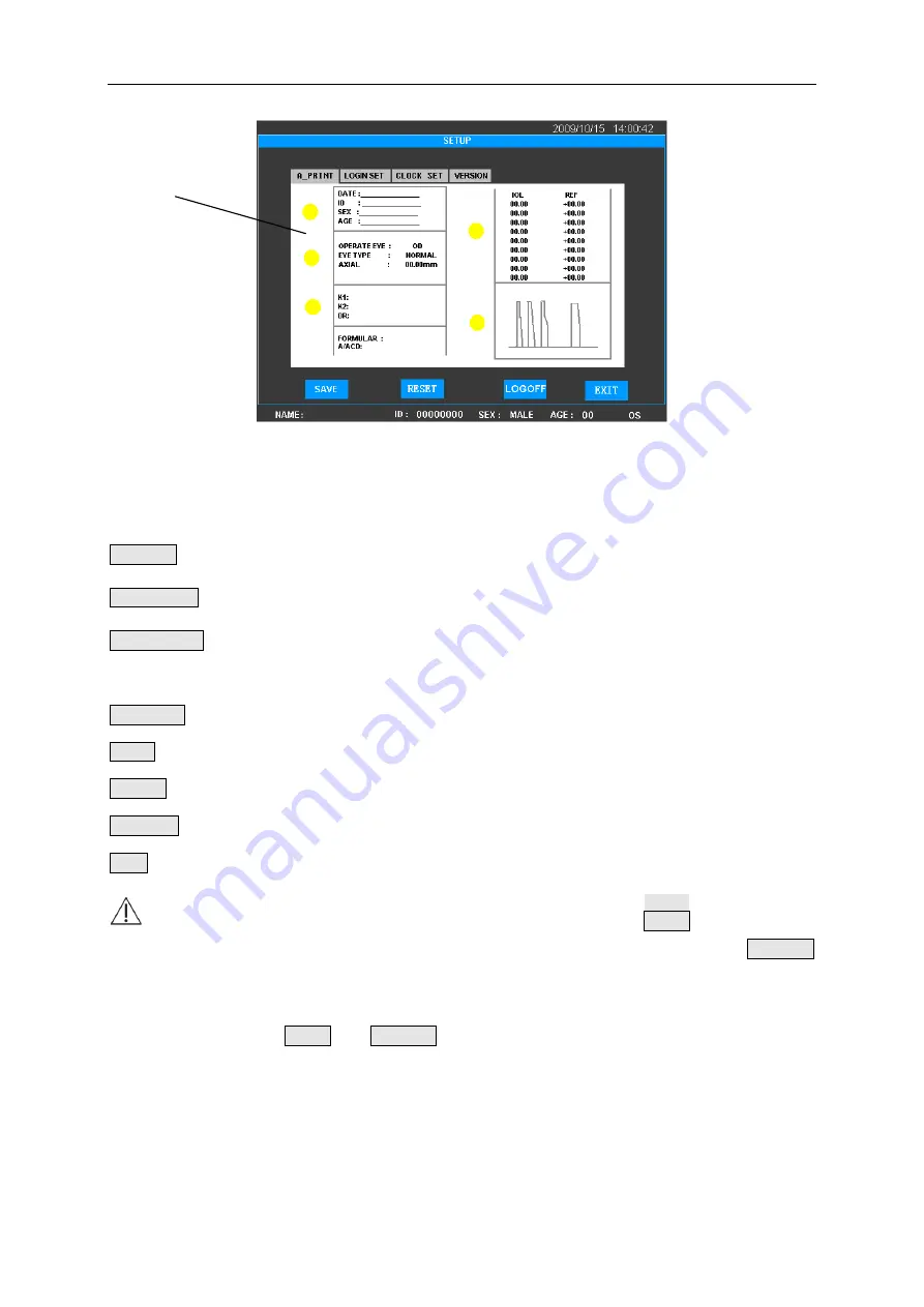
Figure 4.11 SETUP Interface


The Setup Interface consists of three parameter setup tab pages. Click the corresponding key to 
enter each tab page. 

A-PRINT: Click it to enter the print parameter tab page for A Biometer;   

LOGIN SET : Click it to enter the user setup tab page (it is not available under ADMIN system). 

CLOCK SET: Click it to enter the clock setup tab page; 

The functions of other keys under the SETUP Interface are as follows: 

VERSION: Click it to enter version information tab page; 

SAVE: Click it to save selected result; 

RESET

Reset key. Click it to restore default value; 

LOGOFF: Click it to cancel the system and reenter into the Login Interface after 1 second; 

EXIT: Click it to exit from the interface. 

 Note

1) Under other tab pages except that of CLOCK SET, click SAVE key will save all 

parameters in the A-PRINT and LOGIN SET tab pages; and click PRESET 

key will restore all parameters to default settings. Please confirm before 

operation. 

2) Click SAVE or PRESET key will save the status of all parameters 

automatically, so please make the related change cautiously. 

4.2.7.  DATA BASE Interface 

The DATA BASE Interface is for patient information management, as shown in Figure 4.12. 

Tab Page 

Summary of Contents for GRU-5000 A

Page 1: ......

Page 2: ...Address 9990 NW 14ST Suite 105 Doral FL 33172 Phone 1 888 334 4640 Fax 1 786 621 1842 Email info gilras com...

Page 3: ...orage Conditions 2 2 4 2 Transportation Conditions 3 2 5 CLASSIFICATION 3 CHAPTER 3 INSTALLATION 4 3 1 STRUCTURE 4 3 2 ENVIRONMENTAL REQUIREMENTS 5 3 3 CONNECTION 5 3 3 1 Connection of Probe 5 3 3 2 D...

Page 4: ...N OF THE PROBES 34 5 4 PREPARATION OF STERILIZATION AGENT 35 5 5 STANDARD METHOD 36 FOR U S A 39 5 6 CLEANING OF THE MAIN UNIT OF GRU 5000A 39 5 7 HOW TO PREVENT CROSS INFECTION 39 5 8 METHOD 39 5 8 1...

Page 5: ...TATEMENT 48 A 2 PRINCIPLE OF ALARA AS LOW AS REASONABLY ACHIEVABLE 48 ANNEX B PROMPT MESSAGE 49 ANNEX C 1 ACOUSTIC OUTPUT REPORT IEC60601 2 37 50 ANNEX C 2 ACOUSTIC OUTPUT REPORTING TABLE 51 ANNEX D G...

Page 6: ...meets the safety standard of medical electrical devices If damaged contact the Manufacturer to purchase Use of other adaptors may cause safety risk The manufacturer won t be responsible for any damag...

Page 7: ...tential hazards are contained in the User Manual Please maintain vigilance at any time to those unpredictable hazards The manufacturer won t be responsible for damages and losses caused by negligence...

Page 8: ...splayed with a minus sign Do not ignore this sign _____________________ TISSUE EXPOSURE TO ULTRASOUND ENERGY The GRU 5000 is designed for use in ophthalmology only While the manufacturer is not aware...

Page 9: ...Printer Rear Panel Symbol of Type B Refer to User Manual Serial Number CE Mark Manufacturer FOOT SWITCH Foot Switch Socket Power Input Socket Right Panel A Probe A Biometric Probe Socket User Manual...

Page 10: ...l Printer used to print out patient information A Scan measuring waveform IOL calculating parameter and result The built in memory of the GRU 5000A can store up to 180 patients records 1 2 Intended Us...

Page 11: ...ng mode automatic mode or manual mode can be selectable Automatic mode for Normal Cataract and Aphakic mode Measuring method contact and immersion can be selectable IOL calculation SRK T SRK II BINK I...

Page 12: ...e of protection against electric shock Type B As per the degree of protection against ingress of liquids Main unit IPX0 Part of Probe that can be immersed IPX7 Foot switch IPX1 As per the disinfection...

Page 13: ...ge of AC100 240V and output voltage of DC12V 4A meets the safety requirements of medical electric device as shown in Figure 3 3 Figure 3 3 Power Adaptor DC Power Input Plug Power Adaptor DC Power Inpu...

Page 14: ...therapy equipment etc 7 Please do not put the instrument in a place where it is difficult to disconnect the power supply 8 The instrument should be placed in a position where the operator can face the...

Page 15: ...lug the DC Power Output Plug of the Power Adaptor in the Power Input Socket on the rear panel of the instrument 2 Connect one end of the Power Cable with the Power Adaptor and the other end to the wal...

Page 16: ...ess OPEN button to open the cover of the paper housing 2 Take out the reel of the paper from the paper holder and add new paper see Figure 3 6 Figure 3 6 Replacement of Printing Paper 3 Pull out the p...

Page 17: ...lights up whether the Power Cable is intertwined with other cables 4 1 2 Startup Procedure 1 Make sure there is no problem and the Power Indicator lights up before the instrument is started 2 Start th...

Page 18: ...cable is placed properly to prevent others from stumbling by the cable and drop of instrument 3 Plug out the Main Power Plug of the Power Adaptor cable and put it properly 4 2 Interface Introduction...

Page 19: ...Area The result of measurement display area Waveform Display Area ASCAN ultrasonic echo waveform display area Patient Information Display Area Display the input patient information Click this area to...

Page 20: ...ed while green indicates scanning Up and Down keys used to adjust the position and value The keys are used to adjust the position of the Threshold Line when the Threshold Line displayed and to adjust...

Page 21: ...ormation Display Area at the bottom of the screen to enter the Patient Information Interface directly The Patient Information Interface is used to input patient information including patient name ID a...

Page 22: ...ick it the Patient ID will be restored to default value new patient information can be input at the moment meanwhile all data measured in other interfaces will be cleared MENU MENU key Click it to ret...

Page 23: ...Interface SETUP Interface and DATA BASE Interface 4 2 5 IOL Interface The IOL Calculation Interface as shown in Figure 4 7 The keypad at the bottom of the interface is used to input numbers AL Axial L...

Page 24: ...wn menu Select the desired formula and input parameters The formulas provided are SRK II SRK T HOLLADAY HOFFER Q HAIGIS BINK II and IOL calculation formulas after corneal refractive surgery HISTORY DE...

Page 25: ...parameter dialogue box K2pre Keratometry before corneal refractive surgery A Constant of IOL click it to call out Constant A ACD Input Dialogue Box REFRpre Refraction before corneal refractive surgery...

Page 26: ...hange as shown in Figure 4 10 Figure 4 10 IOL Calculation Interface MEM Memory key click it to save all the related information including the patient information measuring data waveform and IOL calcul...

Page 27: ...ge SAVE Click it to save selected result RESET Reset key Click it to restore default value LOGOFF Click it to cancel the system and reenter into the Login Interface after 1 second EXIT Click it to exi...

Page 28: ...lected information only All deletions are not recoverable please operate cautiously Click EXIT key to exit 4 3 Operation 4 3 1 Positioning Place the instrument beside the patient The distance between...

Page 29: ...m separately to acquire measuring data The measuring method and eye model selection are invalid In MANUAL mode The operator can mark the position of the arrow manually according to the selected measur...

Page 30: ...fer to item d of this section d MODE SETTING dialogue box Click NORM key to call out the dialogue box as shown in Figure 4 14 The dialogue box consists of three parts namely measuring mode setting mea...

Page 31: ...of the tissue interface sharp front edge is preferred e When the probe is properly aligned you will hear a series of beep sounds the waveform is automatically frozen and data will be displayed on the...

Page 32: ...omatic measurement The rest operations are the same with that of the CONTACT method 4 3 2 4 Threshold modification under the AUTO mode The threshold can be set according to the actual demand The thres...

Page 33: ...ode c Move the probe slightly to observe the reflected waveform When the reflected waveform is clear click SCAN FREEZE key again or step on the foot switch to freeze the waveform The first group of wa...

Page 34: ...inguish the posterior segment of the cornea then move the arrow to the reflected waveform s rising edge of the posterior segment of the cornea click ENTER key then the cornea thickness is input in the...

Page 35: ...terface see 4 2 5 In the IOL Interface the measuring result of AL can be acquired by the calculation interface directly or be input manually Select the required formula by clicking the Formula Selecti...

Page 36: ...or ACD can call out the Constant A ACD Input Dialogue Box meanwhile the selected key turns to green indicating the status of selected as shown in Figure 4 20 In the Constant A ACD Input Dialogue Box...

Page 37: ...turns to blue Click OK to exit Click CAL key to make calculation after all parameters are input The calculating result will display on the screen The operator can select to print out or save the resul...

Page 38: ...peration Select YES to confirm clearance of all data The data cleared are not recoverable Select NO to exit without clearing Click DELETE key to delete one patient s information The use of DELETE key...

Page 39: ...he newly input parameters and calculated result can t be saved If measurement or storage of new data is required please return to the normal working interface To exit from the IOL Interface it s requi...

Page 40: ...or cancel printing synchronously 4 3 5 2 LOGIN SET Parameter Setup Unavailable under ADMIN System Under startup selection the default system is ADMIN click ENTER key directly to enter If ADMIN is sele...

Page 41: ...ions of SAVE and RESET will save all parameters in A_PRINT and LOGIN SET tab pages or reset all settings to initial values Please confirm before the operation 4 3 5 3 Clock Set Figure 4 26 CLOCK SET I...

Page 42: ...ppears on the top right corner to display time Click RESET key to restore to zero Click EXIT key once to exit from the clock editing status double click EXIT key to exit from the dialogue box 4 3 5 4...

Page 43: ...ommercial disinfectants The surface should then be dried with lint free cloth 5 2 Cleaning Disinfection of Eye Cup The following procedure of disinfection is suggested for the eye cups we provided 1 I...

Page 44: ...diluted at 5 with distilled water The solution must be changed every day 6 Chlorometric degree solution of sodium hypo chloride at 20 The contents of the tray must be changed after each use Demineral...

Page 45: ...if kept in sealed flask Please pour in soaking tray 500ml when sterilization is necessary Replacing Contents of soaking trays For frequent use the contents of the trays should be replaced at the begi...

Page 46: ...d water keeping the connectors dry 6 Drying Dry it with a sterile compress 7 Now the probe is ready for use METHOD FOR HIGH RISK PATIENTS NOTES Please disconnect the probes from the machines Machines...

Page 47: ...n a 6 chlorometric degree solution hypochloride for 60 min at 20 keeping the connectors dry D Rinsing 5 Rinse the probe and the cable with demineralized or distilled water E Disinfection 6 Dry with a...

Page 48: ...ment 2 Do not immerse the instrument in disinfectant solution 5 7 How to Prevent Cross Infection The probe and eye cup that are intended to come in contact with mucous membranes belong to semi critica...

Page 49: ...nd or eye cup and wipe it with sterile cloth Note 1 Disposable gloves eye protection and liquid proof gowns should be worn when cleaning soiled probe and or eye up 2 All detail information for Bianex...

Page 50: ...ally c After disinfection processing put the A Probe and or eye cup into a sterile box Now the A Probe and or eye cup are ready for use Note 1 Steam sterilization is prohibited 2 Disconnect the probe...

Page 51: ...External Label 1 Printing Paper Packaging Label Figure 6 1 Printing Paper Packaging Label 2 Probe Socket Label Figure 6 2 Probe Socket Label 6 2 Internal ID 1 Button cell CR2032 3V lithium cell Figur...

Page 52: ...long time it should be power on for one hour per month to get the damp out 7 Avoid drop or severe shock when moving the instrument Give particular attention to protect the probe 8 Do not block the ven...

Page 53: ...e is well connected 9 The probes provided with the instrument should be used in the instrument only and not be used for other purposes 7 3 Maintenance of LCD Screen 1 Clean the LCD screen with glasses...

Page 54: ...rt check if it is back to normal 5 In case of overheat or other abnormalities please switch off the mains power immediately to prevent danger 6 The over current protection fuse is sealed inside the po...

Page 55: ...1 Consumables SN Description Manufacturer Model Specification 1 Printing Paper Beijing Xun Pu Electronic Technology Company 57mm 40mm Thermal Printing Paper 8 2 2 Detachable Parts SN Description Mode...

Page 56: ...ormation 47 free software update service For the expansion of software functions the manufacturer will provide users with software update information and according to users demand provide software upd...

Page 57: ...be implemented to perform ultrasound procedure Try to use lowest level of energy that will not result in biological effect The ultrasonic energy depends on acoustic output intensity and exposure time...

Page 58: ...YOU SURE TO SAVE prompts to confirm saving or not ARE YOU SURE TO DELETE prompts to confirm deletion or not ARE YOU SURE TO CLEAR ALL THE DATA PERMANENTLY prompts the cleared data are not recoverable...

Page 59: ...ded output power P1 Attenuated output power P 1 86 Attenuated spatial peak temporal average intensity Ispta Attenuated peak rarefactional acoustic pressure pr 0 24 12dB output beam area Aaprt Break po...

Page 60: ...index value 0 079 0 003 1 68 Associated acoustic parameter Pr 3 MPa 0 241 W0 Mw 0 00035 0 00035 fc MHz 9 203 9 203 9 203 ZSP cm 2 10 2 10 2 10 Beam dimensions x 6 cm 0 169 0 169 y 6 cm 0 162 0 162 PD...

Page 61: ...Annex D Guidance and Manufacturer s Declaration 52 Annex D Guidance and Manufacturer s Declaration...

Page 62: ...Annex D Guidance and Manufacturer s Declaration 53...

Page 63: ...Annex D Guidance and Manufacturer s Declaration 54...

Page 64: ...Annex D Guidance and Manufacturer s Declaration 55...

Page 65: ...values before corneal refractive surgery and the lens power of spectacles before and after corneal refractive surgery that is to input all parameters of K1pre K2pre REFRpre and REFRpost in the dialogu...

Page 66: ...SHAMMAS SHAMMAS Remarks 1 means the parameter is applicable to this formula and means not applicable The shaded area in the table is applicable to cases without refractive surgery 2 The parameters of...

Page 67: ...RETZLAFF J KRAFF MC Comparison of the SRK II formula and other second generation formulas J Cataract Refract Surg 14 136 141 1988 HOFFER KJ The effect of axial length on posterior chamber lens and pos...

Page 68: ......

Reviews: