


- 21 -
Hardware Installation
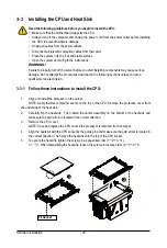
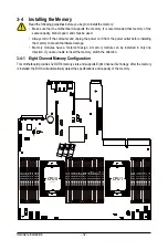
2-3 Front Panel LED and Buttons
L1
L2
1
3
5
7
2
4
6
8
No. Name
Color
Status
Description
1.
Reset Button
Press the button to reset the system.
2.
NMI button
Press the button server generates a NMI to the processor
if the multiple-bit ECC errors occur, which effectively halt
the server.
3.
Power button
with LED
Green
On
System is powered on
N/A
Off
•
System is not powered on or in ACPI S5 state (power
off)
4.
ID Button
with LED
Blue
On
System identification is active.
N/A
Off
System identification is disabled.
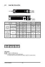
5.
HDD Status
LED
Green
On
HDD locate
Blink HDD access
Amber
On
HDD fault
Green/
Amber
Blink HDD rebuilding
N/A
Off
No HDD access or no HDD fault.
6.
System
Status LED
Green
On
System is operating normally.
Amber
On
Critical condition, may indicates:
System fan failure
System temperature
Blink
Non-critical condition, may indicates:
Redundant power module failure
Temperature and voltage issue
Chassis intrusion
N/A
Off
Non-critical condition, may indicates:
Redundant power module failure
Temperature and voltage issue
Chassis intrusion
Summary of Contents for R282-3C0
Page 9: ... 9 5 8 BIOS POST Beep code AMI standard 113 5 8 1 PEI Beep Codes 113 5 8 2 DXE Beep Codes 113 ...
Page 10: ... 10 This page intentionally left blank ...
Page 18: ...Hardware Installation 18 This page intentionally left blank ...
Page 26: ...Hardware Installation 26 This page intentionally left blank ...
Page 31: ... 31 Hardware Installation 5 1 3 2 4 6 4 3 ...
Page 42: ...Hardware Installation 42 On board SATA Cable SATA1 SATA4 SATA5 Onboard SATA Cable SATA4 SATA5 ...
Page 43: ... 43 Hardware Installation NVMe Cable USB Cable ...
Page 44: ...Hardware Installation 44 B P Cable F P Cable ...
Page 45: ... 45 Hardware Installation HDD BP Power HDD BP Signal ...
Page 46: ...Hardware Installation 46 3 9 2 R282 3C1 USB Cable F P Cable ...
Page 47: ... 47 Hardware Installation B P Cable NVMe Cable ...
Page 48: ...Hardware Installation 48 SAS HDD HDD B P Signal ...
Page 49: ... 49 Hardware Installation RAID CARD RAID Card SAS_IN0 SAS_IN1 HDD BP Power ...
Page 50: ...Hardware Installation 50 This page intentionally left blank ...
Page 56: ...Hardware Installation 56 This page intentionally left blank ...
Page 77: ... 77 BIOS Setup 5 2 12 Intel R i350 Gigabit Network Connection ...
Page 82: ...BIOS Setup 82 5 3 1 Processor Configuration ...
Page 118: ...BIOS Setup 118 This page intentionally left blank ...