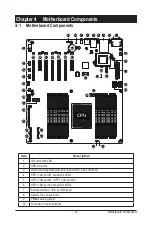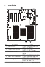
Motherboard Components
- 38 -
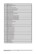
11
PMBus connector
12
BMC firmware readiness LED
13
TPM connector
14
2 x 12 pin main power connector
15
2 x 4 pin power connector (for memory)
16
2 x 4 pin power connector (for CPU)
17
CPU fan connector #1
18
CPU fan connector #0
19
Clearing Supervisor Password jumper
20
BIOS recovery jumper
21
Slimline connector #0 (SATA 6Gb/s signal)
22
Slimline connector #1 (SATA 6Gb/s signal)
23
Slimline connector #2 (SATA 6Gb/s signal)
24
Slimline connector #3 (SATA 6Gb/s signal)
25
Front panel header
26
HDD back plane board header
27
M.2 slot (Gen 3/x4)
28
USB 3.0 header
29
System Fan connector #1
30
USB 2.0 header
31
System Fan connector #4
32
System Fan connector #5
33
System Fan connector #2
34
Serial port cable connector
35
PCIe x16 slot (Gen 3/x16)
36
PCIe x8 slot (Gen 3/x8)
37
PCIe x16 slot (Gen 3/x16)
38
PCIe x16 slot (Gen 3/x16)
39
PCIe x8 slot (Gen 3/x8)
40
PCIe x16 slot (Gen 3/x16)
41
PCIe x8 slot (Gen 3/x8)
42
Battery socket
43
IPMB connector
44
Clear CMOS jumper
Summary of Contents for R271-Z31
Page 1: ...R271 Z31 AMD EPYC 7003 UP Server System 2U 16 Bay User Manual Rev 1 0 ...
Page 10: ... 10 This page intentionally left blank ...
Page 16: ...Hardware Installation 16 This page intentionally left blank ...
Page 22: ...System Appearance 22 This page intentionally left blank ...
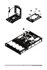
Page 27: ... 27 System Hardware Installation 6 7 4 1 3 2 5 ...
Page 40: ...Motherboard Components 40 This page intentionally left blank ...
Page 46: ...BIOS Setup 46 When Boot Mode Select is set to Legacy in the Boot Boot Mode Select section ...
Page 59: ... 41 BIOS Setup 5 2 8 PCI Subsystem Settings ...
Page 70: ...BIOS Setup 70 5 2 17 QLogic 577xx 578xx 10 Gb Ethernet ...
Page 72: ...BIOS Setup 72 5 2 17 1 Firmware Image Menu ...
Page 139: ... 41 BIOS Setup This page intentionally left blank ...

