


- 19 -
System Appearance
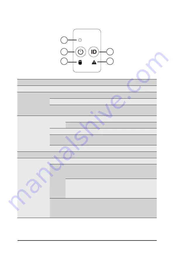
2-3 Front Panel LED and Buttons
RST
1
2
3
4
5
No. Name
Color
Status
Description
1.
Reset Button
--
--
Press the button to reset the system.
2.
Power button
with LED
Green
On
Indicates the system is powered on.
Green
Blink
System is in ACPI S1 state (sleep mode).
N/A
Off
•
System is not powered on or in ACPI S5 state (power off)
•
System is in ACPI S4 state (hibernate mode)
3.
HDD Status
LED
Green
On
Indicates locating the HDD.
Blink
Indicates accessing the HDD.
Amber
On
Indicates HDD error.
Green/
Amber
Blink
Indicates HDD rebuilding.
N/A
Off
Indicates no HDD access or no HDD error.
4.
ID Button
Press the button to activate system identification
5.
System
Status LED
Green
On
Indicates system is operating normally.
Amber
On
Indicates a critical condition, may include:
-System fan failure
-System temperature
Blink
Indicates non-critical condition, may include:
-Redundant power module failure
-Temperature and voltage issue
-Chassis intrusion
N/A
Off
Indicates system is not ready, may include:
-POST error
-NMI error
-Processor or terminator is missing
Summary of Contents for G262-ZR0
Page 1: ...G262 ZR0 HPC Server 2U DP SXM4 A100 4 GPU Server User Manual Rev 1 0 ...
Page 10: ... 10 This page intentionally left blank ...
Page 37: ... 37 System Hardware Installation HDD Back Panel Board NVMe Signal Cable ...
Page 38: ...System Hardware Installation 38 PCIe Signal Cable ...
Page 39: ... 39 System Hardware Installation System Power Cable Power Supply Signal Cable ...
Page 40: ...System Hardware Installation 40 On Board SATA Cable ...
Page 53: ... 43 BIOS Setup 5 2 4 1 Serial Port 1 Configuration ...
Page 62: ...BIOS Setup 62 5 2 9 PCI Subsystem Settings ...
Page 73: ... 43 BIOS Setup 5 2 18 Intel R Ethernet Controller I350 ...
Page 155: ...BIOS Setup 155 This page intentionally left blank ...


