background image

KDVRAY500 MANUAL 
 

Pag. 9 of 24 


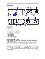
Aeraulic connections 


The machine is equipped with plastic nozzles with gaskets, which protrude about 4 cm and 

which make it possible the connection with flexible or rigid ducts, provided that they are 

equipped with gaskets to avoid air leaks and unpleasant noise. Spigot diameters are as follows: 

supply and recirculation  


Ø 200 

fresh air intake and air exhaust  

Ø 200 

stale air from bathroom/kitchen  

Ø 160 


PLEASE NOTE: the real diameter of the air spigots is approximately 1-2 mm less than the 

nominal diameter. 


ELECTRICAL CONNECTIONS 


CONDUCTOR SIZE  

The electric power supply line and the isolating devices must be decided by qualified staff 

responsible for the electrical design. In any case, the cable must have a minimum cross-section 

of 3x1.5 mm², F + N + PE. 

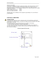
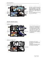
The following diagram shows the terminals which are available for connections: 

the machine must be connected to an electric power supply; 

a 4-wire connection provides the control panel with both the 24VDC power supply and 

the serial communication. This connection cable must have a minimum cross-section of 0.5 

mm² and must be shielded. 


Electronic board onto the machine


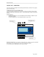
Connection to the control panel


Red led means voltage


Green led


230V power supply 

Summary of Contents for KDVRWY300

Page 1: ...XCHANGE AND HEAT RECOVERY 12 2021 INDEX page TRANSPORT AND STORAGE 2 DESCRIPTION AND MAIN COMPONENTS OF THE UNIT 2 DIMENSIONS 4 INSTALLATION 4 CONNECTIONS 6 OPERATION DESCRIPTION 9 START UP AND TESTIN...

Page 2: ...tacked one on top of the other Ideal environment conditions 10 C 50 C relative humidity lower than 90 NOTE Manual handling must comply with the laws in force DESCRIPTION AND MAIN COMPONENTS OF THE UNI...

Page 3: ...r o cooling compressor p hydraulic connections q condensation drains r electric board Construction characteristics Cooling compressor Hermetic alternative monocylindrical Cooling gas R134a 560g eq CO2...

Page 4: ...of this user manual The machine contains pressurized cooling gas Vent the room in case of gas leaks from one or multiple units The gas contained in the units may create toxic components in case of fir...

Page 5: ...max 18 C Electric power 10 A 230V 50Hz 1ph Condensation drain Flow rate 15 l h Min slant 3 2 siphons required h 40 mm Aeraulic ducts Min diameter same as unit nozzles The losses of pressure inside th...

Page 6: ...ves inside the chilled water pipes to section the system from the machine After connecting the circuit to the system test the water seal of the connections and the unit to prevent damages to the area...

Page 7: ...anned by qualified electric planners the wire must in any case feature a 3x1 5 sq mm min section F N PE The picture below shows the connection terminals available The electric supply must be provided...

Page 8: ...unication line between the control panel and the KDVRWY300 unit a 120 Ohm W terminal resistance must be installed between terminals A and B of the control panel This should be fitted with tape on the...

Page 9: ...flows inside the unit the exchange air flow with heat recovery through the counter current air air recuperator 1 and the room air recirculation flow The exchange and recirculation flows can be either...

Page 10: ...The water supplied coil 3 fed by the radiant system pre cools the air the cooling evaporator 4 provides air cooling and in turn dehumidification The cooling circuit includes two condensers with parall...

Page 11: ...circuit loss of pressure kPa 8 Power absorbed by the delivery fan min max W 15 70 Delivery fan flow rate min max m3 h 80 300 Delivery fan useful hydraulic head Pa 120 Power absorbed by the ejection f...

Page 12: ...1 39 3 29 9 1953 1720 1467 3166 2767 2351 431 457 482 24 65 12 15 18 3358 2945 2504 1818 1654 1488 1540 1291 1016 53 2 44 6 35 1 2107 1877 1621 3270 2881 2465 434 458 483 26 55 12 15 18 3369 2952 251...

Page 13: ...of operation is in progress but the compressor is not controlled yet because it is on hold or malfunctioning The functions available through digital inputs are current season exchange with heat recove...

Page 14: ...damper 9 when available is open both fans are ON the compressor is ON and the entire coil unit treats the inflow air The air flow rate of the inflow air can be set between 160 and 300 mc h while the e...

Page 15: ...low rate can be adjusted through an external 3 way valve optional RECIRCULATION ONLY EXCHANGE RECIRCULATION Damper 10 is open and modulating damper 9 when available is open both fans are ON and the wa...

Page 16: ...nic card the digital inputs of the various functions the two digital relay outlets that activate a circulation pump and a failure signal CONTROL PANEL CONNECTION ModBus CONNECTION this should be perfo...

Page 17: ...been assembled Exchange Air exchange with the corresponding flow rate using the heat recuperator Cooling Displayed when summer is selected the dehumidification cooling compressor is turned ON and the...

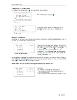
Page 18: ...e triangle cursor to the upper line To move back to the previous screen press The initial screen displayed when the unit is ON will be the following current time current season Initial screen The init...

Page 19: ...E the user can activate the control displayed by YES lock the control displayed by NO or cancel the setting confirmed by two dashes After confirming the setting with E the control duration will be dis...

Page 20: ...time once both times have been defined the time slot will be set HOW TO DELETE A TIME SLOT To delete a time slot set the start and end time on the same value the times will be deleted and the line wi...

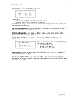
Page 21: ...r delivery temperature can be adjusted while only the hydraulic pump control relays can be activated if there is no modulating valve Season source To decide if the season must be entered by digital in...

Page 22: ...nt by the electronic card on the unit There are two types of messages and they are all coded with a multiple of 2 Failure messages signaling a failing sensor Alarm messages signaling an anomalous oper...

Page 23: ...isk just enter the integration input to restart the unit The other alarms are self deleted when the related issue is solved The control panel displays only one message in case of multiple alarms the d...

Page 24: ...o nell ambiente dell apparecchiatura o lo smaltimento abusivo della stessa sono puniti dalla legge EN IMPORTANT INFORMATION FOR CORRECT DISPOSAL OF THE PRODUCT This product falls into the scope of the...

Page 25: ...T WITH AIR EXCHANGE AND HEAT RECOVERY 05 2022 INDEX TRANSPORT AND STORAGE 2 DIMENSIONS 4 INSTALLATION 4 CONNECTIONS 6 OPERATION DESCRIPTION 9 START UP AND TESTING 12 CONTROL PANEL 16 DIAGNOSTICS 22 MA...

Page 26: ...rs before installing the machine The parcels must be stored upright and in horizontal position and up to three parcels can be stacked one on top of the other Ideal environment conditions 10 C 50 C rel...

Page 27: ...tchboard for control and management LEGEND a air delivery b delivery fan c ejection fan d foul air ejection e room air recirculation f exchange air vacuum g foul air vacuum h damper for separation fro...

Page 28: ...of this user manual The machine contains pressurized cooling gas Vent the room in case of gas leaks from one or multiple units The gas contained in the units may create toxic components in case of fir...

Page 29: ...C Electric power 10 A 230V 50Hz 1ph Condensation drain Flow rate 15 l h min slant 3 2 siphons required h 40 mm Aeraulic ducts Min diameter same as unit nozzles The losses of pressure inside the ducts...

Page 30: ...pipes Insert shut off valves inside the chilled water pipes to section the system from the machine After connecting the circuit to the system test the water seal of the connections and the unit to pr...

Page 31: ...the nozzles is approx 1 mm shorter than the nominal diameter ELECTRIC CONNECTIONS WIRE SECTION The electric supply line and the section devices must be selected by qualified electric planners the wir...

Page 32: ...he control panel and the KDVRAY360 unit be longer than 25 m a 120 Ohm W terminal resistance must be installed between terminals A and B of the control panel The resistance should be fitted with tape o...

Page 33: ...n the flow rates and the type of treatment desired for the inflow air The unit also includes a duct controlled by a motorized damper to vacuum the external air without passing through the recuperator...

Page 34: ...s process the unit exploits the ejected foul air and an additional integration flow of external air The two electronic expansion valves E enable to distribute the condensation heat between the inflow...

Page 35: ...l h 360 Water circuit loss of pressure kPa 12 Power absorbed by the delivery fan min max W 40 170 Delivery fan flow rate min max m3 h 90 360 Delivery fan useful hydraulic head Pa 200 Power absorbed b...

Page 36: ...flow rates normal and integration delivery temperature for each season time slots for automatic exchange max 4 time slots for flow rate attenuation max 4 The operator can also read the values of the u...

Page 37: ...e setting temperature Should it be necessary to dispose the exceeding heat the ejection fan vacuums and ejects the external air flow heated by the exhaust coil The compressor and both fans are ON The...

Page 38: ...are working and perform air exchange the external air is heated first by the recuperator through the ejected air and then by the hot water circulating inside the finned coil is vacuumed and at the se...

Page 39: ...air flow rate can be set between 90 and 360 m3 h while the exchange share can be set between 90 and 220 m3 h The fans are both working the damper of the inflow external air is closed and the bypass da...

Page 40: ...the various functions the two digital relay outlets that activate a circulation pump and a failure signal MODBUS CONNECTION the connection is carried out with 4 threads 2 for the 24VDC supply to the...

Page 41: ...setting limits Attenuation The unit works with the same flow rates of attenuation set by default on lower values compared to normal operation to reduce noise This function is convenient if the user w...

Page 42: ...atus and move the triangle cursor to the upper line To move back to the previous screen press The initial screen when the unit is ON will be the following current time current season Initial screen Th...

Page 43: ...cursor on the line of the desired control using or press E to confirm the function YES block the function NO or cancel the setting two dashes After confirming the setting with E the control duration...

Page 44: ...ined the time slot will be set HOW TO SET A TIME SLOT To delete a time slot set the start and end time on the same value the times will be deleted and the line will display dashes only HOW TO SET THE...

Page 45: ...ion Winter Delivery Temp Air delivery temperatures in winter mode one for the neutral air function and one for the heating integration function Temp Free Cooling temperatures that limit the free cooli...

Page 46: ...ged Sens Failure 512 Differential pressure sensor for exchange air Sens Failure 1024 Differential pressure sensor for ejection air Alarm messages Message Meaning Alarm 1 Unit with no cooling gas perma...

Page 47: ...luded filters may not be suitable Install air filters outside the unit based on the system needs Remove the air filters DEMOLITION AND DISPOSAL In case of demolition of the dehumidifier remember that...

Page 48: ...UCT This product falls into the scope of the Directive 2012 19 EU concerning the management of Waste Electrical and Electronic Equipment WEEE This product shall not be dispose in to the domestic waste...

Page 49: ...ND DEHUMIDIFICATION MODEL KDVRAY500 05 2022 SUMMARY pag TRANSPORT AND STORAGE 2 MACHINE DESCRIPTION AND INTENDED USE 2 DIMENSIONS 5 POSITIONING AND FIXING 6 CONNECTIONS 8 CONTROL UNIT CONNECTIONS 16 C...

Page 50: ...WARNING The machine contains pressurized refrigerant gas In the event of a gas leak from one or more machines ventilate the room In case of fire the gas contained in the machines can develop toxic com...

Page 51: ...ates and the type of treatment to be carried out on the injected air There is also a duct controlled by a motorized shutter which allows the intake of external air without passing through the recupera...

Page 52: ...e from 300 mc h up to 500 mc h fresh air flow rate settable from 160 up to 300 mc h free cooling renewal flow rate settable from 160 to 300 mc h Please note the ambient flow rate is equal to the sum o...

Page 53: ...outwards In carrying out this process the machine uses both exhaust stale air and an additional air flow coming from outside The two electronic expansion valves E allow to distribute the condensation...

Page 54: ...rous situations in the presence of electricity After filling the system with water it is advisable to check that not only the connections but also the machine hydraulic circuit are watertight as these...

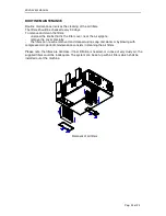
Page 55: ...EPLACEMENT OF THE WHOLE UNIT It is necessary to leave spaces free of obstacles around the machine according to the measurements indicated in the figure below These spaces including that occupied by th...

Page 56: ...to the system a water tightness check must be carried out on both the connections and the machine in order to avoid any damage for the area below the machine Condensate drain There are three condensa...

Page 57: ...e nominal diameter ELECTRICAL CONNECTIONS CONDUCTOR SIZE The electric power supply line and the isolating devices must be decided by qualified staff responsible for the electrical design In any case t...
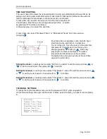
Page 58: ...OF THE CONTROL PANEL It is necessary to insert a termination resistance of 120 Ohm W between terminals A and B of the control panel The resistance is fixed with adhesive tape on the back of the contr...

Page 59: ...apacity for water circuit external air 35 C 50 RH max flow rate for delivery and intake W 2050 Power consumption of the inlet fan min max W 20 160 Inlet fan air flow rate min max mc h 160 500 Availabl...

Page 60: ...ntilation and Ventilation Recirculation mode standard air supply temperature and air temperature for heating and cooling automatic time slots for fresh air ventilation max 4 time slots for flow rate a...

Page 61: ...d the supply fan are running the room air is dehumidified and supplied into the room at the requested temperature A suitable amount of outdoor air is passed through the condenser finned coil by the ex...

Page 62: ...water rate is flowing The air is fed back at the requested temperature the supply fan is running the indoor air is heated in the finned coil the supply air flow rate can be set from 300 to 500 m3 h Th...

Page 63: ...be delivered at the requested temperature by the hot water coil The supply air flow rate can be set from 300 to 500 m3 h the renewal part of it can be set from 160 to 300 m3 h The fans are both runni...

Page 64: ...communication Use a 4 wire shelded cable minimum cross section 0 5 mmq OUTPUT RELAYS C01 NO1 relay 250V AC 5A is activated when water circulation is needed it can be connected to a pump C01 NO2 relay...

Page 65: ...eason DI05 integration mode supplying sensible heat In integration mode unless the renewal contact is closed the recirculation function will start up The integration function acts differently accordin...

Page 66: ...the machine is off the following screen appears To switch from OFF to ON press the button or the button pressing the button E status is confirmed and the cursor moves to the top row to return to the p...

Page 67: ...rs N the related function you can either choose not to modify the function appears Since the setting has been confirmed after pressing the E button you need to set the duration time of the command The...

Page 68: ...e that you can change pressing button or button By pressing E the time is confirmed The same procedure can be made to set the end time To delete a time slot you have to set the end time equal to the s...

Page 69: ...standard mode or heating integration mode Freecooling temperature you can set the values range within freecooling mode will be allowed Freecooling function will be inhibited depending on the outside...

Page 70: ...air supply Sensor Fault 1024 Failure on the flow sensor for stale air Sensor Fault 2048 Failure on the flow sensor for renewal air Alarms messages Displayed Meaning Alarm 1 Refrigeration circuit low p...

Page 71: ...air spigots remove the cover carefully the filters can now be removed and cleaned using soap and water or by blowing with compressed air periodic maintenance consists in cleaning the air filters Pleas...

Page 72: ...sposal of the product is punishable by law FR AVERTISSEMENTS POUR L LIMINATION CORRECTE DU PRODUIT Ce produit entre dans le champ d application de la directive 2012 19 UE relative la gestion des d che...

Reviews: