background image

SECULOGIC T 320

9

Operation

5.2  Open the doors and trigger the alarm in an emergency

By actuating the emergency button, the interlocking elements on the corresponding door are switched off   
(indirect release via TZ 320).

X

X

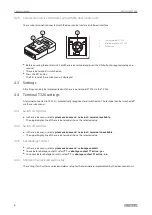
Press emergency button.


à

LED 1 lights up green and LED 3 lights up yellow. The door is unlocked.


à

The alarm is triggered.

5.3  Cancel alarm

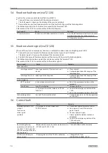
The alarm remains active at the door control unit until the cause of the alarm is eliminated and the alarm on the 
door control unit or terminal is acknowledged.

5.3.1  Reset emergency button

After the emergency situation has been eliminated the emergency button must be reset.

X

X

Remove the cover of the emergency button.

X

X

Turn the emergency button to the right.


à

The emergency button returns to normal state.

X

X

Replace cover.

X

X

Acknowledge alarm.

5.3.2  Acknowledge alarm


Pre

condition: 


à

The cause of the alarm is eliminated.


à

Reset alarm

 is displayed in the service terminal.

Acknowledge alarm and lock door

X

X

Turn the key to the right.

Acknowledge alarm and unlock door

X

X

Turn the key left and hold for approximately one second.

 
The non security-relevant alarms 

emergency unlock

door alarm

 and 

sabotage alarm

 can also be 

acknowledged via the 

Lock

 and 

Unlock

 functions on the TE 220 and VAT 220.

The door alarm can also be acknowledged via the 

short-term unlock

 input of the TZ 320 or KL 220.

A sabotage alarm can only be acknowledged 30 seconds after the cause of the alarm has been eliminated.  

For the duration of the sabotage time the TZ 320 and T 320 are primarily locked. Release via the emergency  

button is possible.

If the alarm cannot be acknowledged by pressing the key-operated push button the a new alarm is possibly 
pending. 

X

X

Check which alarm/fault is pending with the service terminal and correct with the following tables. 

Summary of Contents for SECULOGIC T 320 AP

Page 1: ...1 GEZE SECULOGIC T 320 Emergency Exit System Terminal EN Installation And Commissioning Instructions With Connection Diagram...

Page 2: ...gs 6 4 4 Terminal T 320 settings 6 4 5 Description of basic functions 7 5 Operation 8 5 1 Control the terminal T 320 via key operated push button 8 5 2 Open the doors and trigger the alarm in an emerg...

Page 3: ...these data sheets and other documents as well as the detailed installation and commissioning instructions with connection diagram for the door control unit TZ 320 No 131537 on the internet at www gez...

Page 4: ...tem monthly for externally identifiable damages and defects Such damages and defects if existing must be repaired immediately by a GEZE service technician or a professional organisation authorised by...

Page 5: ...es control of the system 4 Commissioning 4 1 Requirement Before the first commissioning of doors with electric locking mechanisms in the escape routes correlation with verification of suitability is t...

Page 6: ...automatically recognised and switched on The terminal can be switched off via the service menu 4 4 1 Switch on terminal X X In the service menu select system environment terminal terminal available T...

Page 7: ...short term release If the door is closed during a pending door alarm it is locked and can only be unlocked again when the alarm has been reset except with actuation of the emergency button or with eme...

Page 8: ...can be opened X X Turn the key left and hold for approximately one second LED 1 flashes green The door is unlocked Note The Unlock function can be disabled via the service menu system environment SCT...

Page 9: ...ge alarm 5 3 2 Acknowledge alarm Precondition The cause of the alarm is eliminated Reset alarm is displayed in the service terminal Acknowledge alarm and lock door X X Turn the key to the right Acknow...

Page 10: ...ause Remedy Sabotage alarm sabotage contact TT Sabotage contact of the terminal is not closed X X Close contact X X Acknowledge alarm after expiry of the sabotage time sabotage time runs Sabotage time...

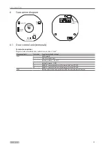
Page 11: ...l connections Plug and screw terminals max cable cross section 1 mm Clamping field Terminal Function default setting X100 1 GND supply 3 24 V DC supply unit 7 Indirect release 24 V DC 8 Indirect relea...

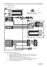
Page 12: ...sh button key operated push button access control Caution Disconnect red bridge 1 7 in FT 331U or Door contact X106 orange terminal strip Locking mechanism Locking mechanism Door locked 24 V DC Door c...

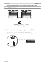
Page 13: ...e Indirect release Indirect release Indirect release 24 V DC supply GND supply 24 V DC GND 6 3 Connection of external key operated push button to T 320 Connection of the key switch to the T 320 is onl...

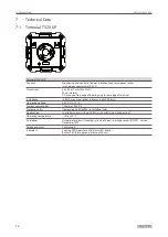
Page 14: ...allation in flush mounted socket 60 mm depth 62 5 mm Operating voltage 24 V DC 10 Current consumption 100 mA at 24 V DC Protection class II according to EN 60950 in installed state Application In inte...

Page 15: ...Operating voltage 24 V DC 10 Current consumption 100 mA at 24 V DC Protection class II according to EN 60950 Application In interior spaces with up to 85 air humidity non condensing Operating temperat...

Page 16: ...0 71 E Mail france fr geze com Hungary GEZE Hungary Kft Bart k B la t 105 113 Budapest H 1115 Tel 36 1 481 4670 Fax 36 1 481 4671 E Mail office hungary geze com Iberia GEZE Iberia S R L Pol Ind El Pla...

Reviews: