SECULOGIC T 320
11
6
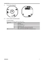
Connection diagram
Door
state
LED
Buzzer
Emergency
button LED
Alarm LEDs
Locking LED
Sabotage
contact
Programming
interface
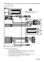
6.1 Door control unit (terminals)
Terminal connections
Plug and screw terminals, max. cable cross section: 1 mm²
Clamping field
Terminal
Function (default setting)
X100
1
GND supply
3
24 V DC supply unit
7
Indirect r 24 V DC
8
Indirect release - GND
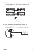
41
R5485-B, communication with door control unit TZ 320
42
R5485-A, communication with door control unit TZ 320
X103
Ribbon cable plug connector for GEZE key-operated push button


