7.2. Emergency Stop Switch
An emergency stop switch is available as an option, installed outside but nearby the
UPS, for stopping the UPS output in case of emergency, such as electrical shock,
burning of the load or any emergency conditions where one wants to stop the AC
output immediately. When the emergency stop switch button is pushed, the inverter
immediately stops running, but the static switch remains tied to the inverter.
Therefore there will be no AC supply at the output. This shutdown condition will be
latched until it is manually reset by pressing the OFF (
0
) switch and inverter
control switch (
WX
) simultaneously.
7.3. Remote Control Panel – UPSCAN
™
UPSCAN
™
is a hand held display module with
LCD (the same as the LCD of the UPS). The
UPSCAN
™
can monitor 1 to 99 UPSs with DB9
connections in series from distance of up to
1000M.
7.4. Software for PC Monitoring – UPSCOM
™
UPSCOM
™
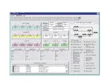
is a hardware/software combination installed on a PC to monitor
multiple UPSs with DB9 connection in series. The connector on the UPS’s side is
RS-485 (for long distance transmission); therefore an RS-485
Ù
RS-232 adapter
(hardware) is required to modify the signal. The software and hardware together
form a package called UPSCOM
™
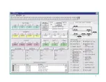
. The UPSCOM
™
PC screen is shown in the
Appendix.
7-2
Summary of Contents for T3UPS-13-20K
Page 18: ...1 7 Dimension Drawings 10KVA 60KVA OUTLINE DRAWING 1 13...
Page 19: ...10KVA 60KVA INTERIOR DRAWING 1 14...
Page 20: ...75KVA 160KVA OUTLINE DRAWING 1 15...
Page 21: ...75KVA 160KVA INTERIOR DRAWING 1 16...
Page 22: ...175KVA 320KVA OUTLINE DRAWING 1 17...
Page 23: ...175KVA 320KVA INTERIOR DRAWING 1 18...
Page 24: ...INTER PCB DIAGRAM 1 19...
Page 31: ...1...
Page 35: ...3 3...
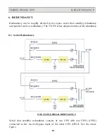
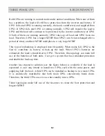
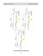
Page 70: ...ONE TO TWO SERIAL REDUNDANCY 8 3...
Page 77: ...Appendices Additional Data on Options UPSCOMTM UPSCALLTM DCMANTM...
Page 80: ...3...
Page 81: ......

