3. INSTALLATION
3.1. Site & Environment Considerations
The main function of the UPS is to provide an safe, clean independent electrical
supply to the load so that it is free from any random variations, disturbances or
interruptions of the utility Mains. The UPS also provides a constant power supply
which is perfectly regulated in both voltage and frequency. And when the Mains are
not available, the UPS can provide optimal back-up time depending on the battery
bank capacity connected to it.
Usually the life expectancy of the UPS is 5 to 10 years (batteries are not included,
because life expectancy of batteries depend on the type of battery, the temperature and
humidity of the environment in which it is installed, and the type of charger that is
applied to the battery). Therefore optimal life expectancy of the UPS can be achieved
by careful consideration of the site and environment.
The following precautions and recommendations should be checked in considering the
site and environment of the UPS:
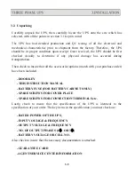
(a) The UPS should be located in a place with adequate ventilation (refer to the
specification of the heat dissipation of the UPS). If the UPS is installed indoors,
care must be taken in insuring the evacuation of heat from a closed room.
(b) Adequate space (at least 1M) should be allowed to open the door, unobstructed
by other objects, for operation or maintenance. Adequate space (at least 1M)
should be allowed at the top of the UPS, because heat dissipation is ventilated
through the top openings.
(c) Do not put any objects on the top of the UPS that may obstruct ventilation. Do
not locate the UPS near any heat source, machinery which produce metallic dust
or powder, or any facility that will produce corrosive substances or vapor.
(d) Protect the UPS from accidental damage from fire extinguishing (sprinkler)
systems. Protect the UPS from abnormal conditions with a dedicated cutoff from
the incoming power.
3-1
Summary of Contents for T3UPS-13-20K
Page 18: ...1 7 Dimension Drawings 10KVA 60KVA OUTLINE DRAWING 1 13...
Page 19: ...10KVA 60KVA INTERIOR DRAWING 1 14...
Page 20: ...75KVA 160KVA OUTLINE DRAWING 1 15...
Page 21: ...75KVA 160KVA INTERIOR DRAWING 1 16...
Page 22: ...175KVA 320KVA OUTLINE DRAWING 1 17...
Page 23: ...175KVA 320KVA INTERIOR DRAWING 1 18...
Page 24: ...INTER PCB DIAGRAM 1 19...
Page 31: ...1...
Page 35: ...3 3...
Page 70: ...ONE TO TWO SERIAL REDUNDANCY 8 3...
Page 77: ...Appendices Additional Data on Options UPSCOMTM UPSCALLTM DCMANTM...
Page 80: ...3...
Page 81: ......


