5-8
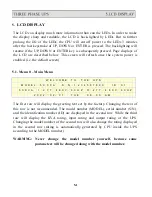
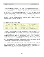
5.8. Menu 7 – Output Data Menu
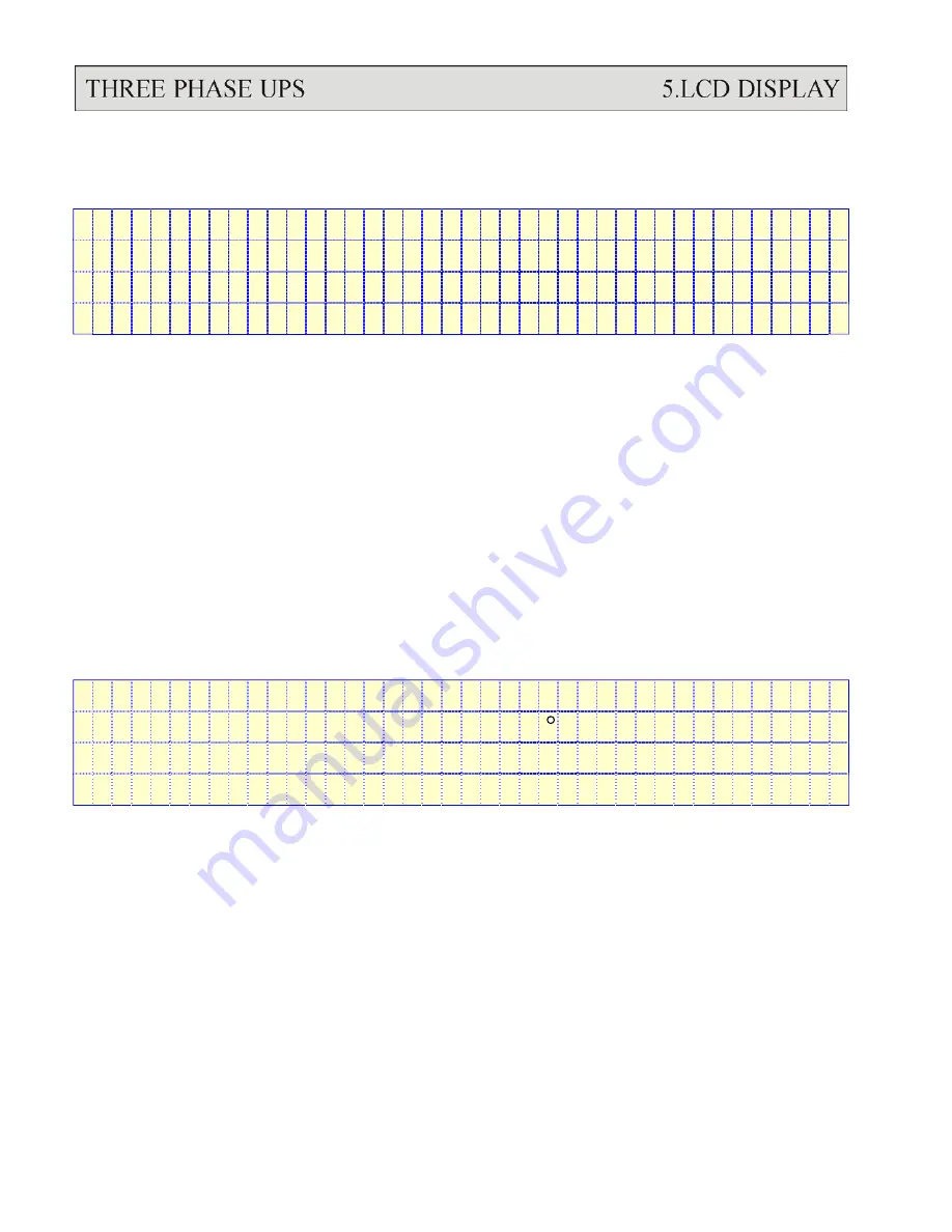
<
O U T P U T
D A T A
>
O U T P U T
F R E Q U E N C Y = X X
H Z
L O A D : R = X X X
% S = X X X
% T = X X X
%
R - N = X X X
V a c
S - N = X X X
V a c
T - N = X X X
V a c
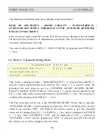
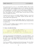
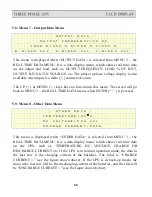
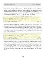
This menu is displayed when <OUTPUT DATA> is selected from MENU 3 – the
REAL TIME DATA MENU. It is a data display menu, which shows real time data
on the output and load, such as, OUTPUT FREQUENCY, LOAD % OF R/S/T,
OUTPUT R-N/S-N/T-N VOLTAGE, etc. The phase to phase voltage display is also
available when input is a delta (
△
) connected source.
The UP (
↑
) or DOWN (
↓
) keys have no function in this menu. The screen will go
back to MENU 3 – the REAL TIME DATA menu, when ENTER(
←┘
) is pressed.
5.9. Menu 8 – Other Data Menu
<
O T H E R
D A T A
>
T E M P E R A T U R E = X X C
D C V O L T A G E = X X X
V d c
C H A R G E
C U R R E N T = X X X A
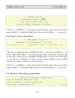
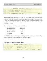
This menu is displayed when <OTHER DATA> is selected from MENU 3 – the
REAL TIME DATA MENU. It is a data display menu, which shows real time data
on the UPS, such as, TEMPERATURE, DC VOLTAGE, CHARGE OR
DISCHARGE CURRENT etc. If the UPS is in normal operation mode, the data in
the last row is the charging current of the batteries. The label is “CHARGE
CURRENT =” (see the figure shown above). If the UPS is in back-up mode, the
data in the last row will be the discharging current of the batteries, and the title will
be “DISCHARGE CURRENT =” (see the figure shown below).
Summary of Contents for T3UPS-13-20K
Page 18: ...1 7 Dimension Drawings 10KVA 60KVA OUTLINE DRAWING 1 13...
Page 19: ...10KVA 60KVA INTERIOR DRAWING 1 14...
Page 20: ...75KVA 160KVA OUTLINE DRAWING 1 15...
Page 21: ...75KVA 160KVA INTERIOR DRAWING 1 16...
Page 22: ...175KVA 320KVA OUTLINE DRAWING 1 17...
Page 23: ...175KVA 320KVA INTERIOR DRAWING 1 18...
Page 24: ...INTER PCB DIAGRAM 1 19...
Page 31: ...1...
Page 35: ...3 3...
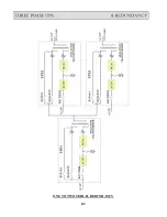
Page 70: ...ONE TO TWO SERIAL REDUNDANCY 8 3...
Page 77: ...Appendices Additional Data on Options UPSCOMTM UPSCALLTM DCMANTM...
Page 80: ...3...
Page 81: ......

