EB-GS2972
Evaluation Board User Guide
50283 - 2
May 2012
6 of 22
NOTE: Some signals are active LOW so that you will need to switch the bit OFF to
activate the signal.
Refer to the GS2972 Data Sheet for definitions of each bit.
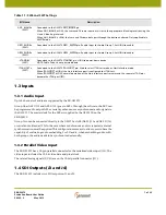
Table 1-1: SW6 and SW7 Settings
Bit Name
Description
TIM861
(
S
W6)
Connected to the G
S
2972 TIM_861 pin. Used to select external CEA-861 timing mode.
When DETECT_TR
S
is LOW and TIM-861 is LOW, the device extracts all internal timing from the supplied H:V:F
timing signals. When DETECT_TR
S
is LOW and TIM-861 is HIGH, the device extracts all internal timing from the
supplied H
S
YNC, V
S
YNC, DE timing signals.
When DETECT_TR
S
is HIGH, the device extracts all internal timing from TR
S
signals em
b
edded in the supplied
video stream.
S
MPTE_BYPA
SS
n
(
S
W6)
Connected to the G
S
2972
S
MPTE_BYPA
SS
pin. Used to ena
b
le/disa
b
le all forms of encoding/decoding,
scram
b
ling and EDH insertion.
When set LOW, the device operates in Data Through mode (DVB_A
S
I= LOW), or in DVB_A
S
I mode (DVB_A
S
I =
HIGH). No
S
MPTE scram
b
ling takes place and none of the I/O processing features of the device are availa
b
le
when
S
MPTE_BYPA
SS
is set LOW.
When set HIGH, the device carries out
S
MPTE scram
b
ling and I/O processing.
DVB_A
S
I
(
S
W6)
Connected to the G
S
2972 DVB_A
S
I pin. Used to ena
b
le/disa
b
le the DVB-A
S
I data transmission.
When set HIGH, the device will carry out DVB_A
S
I, word-alignment, I/O processing and transmission. The
S
MPTE_BYPA
SS
pin must
b
e set LOW.
When
S
MPTE_BYPA
SS
and DVB_A
S
I are
b
oth set LOW, the device operates in data-through mode.
RATE_
S
EL0,
RATE_
S
EL1
(
S
W6)
Connected to the G
S
2972 RATE_
S
EL0 and RATE_
S
EL1 pins. Used to configure the operating data rate.
IOPROC_EN/DI
S
n
(
S
W6)
Connected to the G
S
2972 IOPROC_EN/DI
S
pin. When IOPROC_EN/DI
S
is HIGH, the I/O processing features of the
device are ena
b
led. When IOPROC_EN/DI
S
is LOW, the I/O processing features of the device are disa
b
led. Only
applica
b
le in
S
MPTE mode.
20
b
it/10
b
itn
(
S
W6)
Connected to the G
S
2972 20
b
it/10
b
it pin. Used to select the input
b
us width.
S
DO_EN/DI
S
n
(
S
W6)
Connected to the G
S
2972
S
DO_EN/DI
S
pin. Used to ena
b
le or disa
b
le the serial digital output stage.
When
S
DO_EN/DI
S
is LOW, the serial digital output signals
S
DO and
S
DO are disa
b
led and
b
ecome
high-impedance.
When
S
DO_EN/DI
S
is HIGH, the serial digital output signals
S
DO and
S
DO are ena
b
led.
DETECT_TR
S
(
S
W7)
Connected to the G
S
2972 DETECT_TR
S
pin. Used to select external HVF timing mode or TR
S
extraction timing
mode.
When DETECT_TR
S
is LOW, the device extracts all internal timing from the supplied H:V:F or CEA-861 timing
signals, dependent on the status of the TIM861 pin. When DETECT_TR
S
is HIGH, the device extracts all internal
timing from TR
S
signals em
b
edded in the supplied video stream.
RATE_
S
EL0
Data Rate
0
0
1
0
1
X
1.485 or 1.485/1.001G
b
/s
2.97 or 2.97/1.001G
b
/s
270M
b
/s
RATE_
S
EL1
Summary of Contents for EB-GS2972
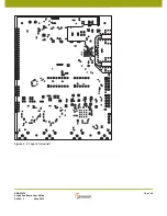
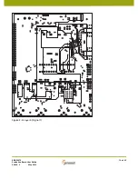
Page 14: ...EB GS2972 Evaluation Board User Guide 50283 2 May 2012 14 of 22 Figure 3 2 Layer 2 Ground ...
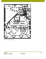
Page 15: ...EB GS2972 Evaluation Board User Guide 50283 2 May 2012 15 of 22 Figure 3 3 Layer 3 Power ...
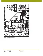
Page 16: ...EB GS2972 Evaluation Board User Guide 50283 2 May 2012 16 of 22 Figure 3 4 Layer 4 Signal 1 ...
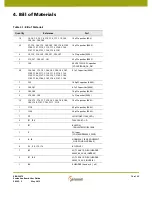
Page 17: ...EB GS2972 Evaluation Board User Guide 50283 2 May 2012 17 of 22 Figure 3 5 Layer 5 Signal 2 ...


