EB-GS2972
Evaluation Board User Guide
50283 - 2
May 2012
5 of 22
1. Board User Guide
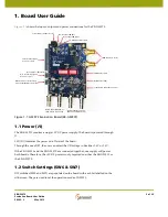
Figure 1-1
shows the inputs, outputs and power connections for the EB-GS2972.
Figure 1-1: G
S
2972 Evaluation Board (EB-G
S
2972)
1.1 Power (J1)
The EB-GS2972 requires a 5V DC power supply. The board is powered through
J1.
LED (D7) indicates the power on/off state of the board.
Through the use of JP7, the user can select the I/O voltage to be either 1.8V or 3.3V.
If the EB-GS2972 and the EB-GS2970 are connected together, one supply will power
both boards. Therefore, the +5V DC power is only required on either the EB-GS2972 or
the EB-GS2970.
1.2 Switch Settings (SW6 & SW7)
DIP switches (SW6 and SW7) are populated on the board with each bit labelled on the
silk-screen. They are used to set the operation mode of GS2972.
Power Supply
C
onne
c
tor (
J
1)
DIP Swit
c
hes (SW
6
& SW7)
Au
d
io Input
G
roup One
(AES 1/
J
13 & AES 2/
J
14)
Au
d
io Input
G
roup Two
(AES 2/
J
115 & AES 2/
J
1
6
)
Parallel Vi
d
eo Input
C
onne
c
tor (
J
25)
H, V & F Timin
g
Si
g
nals
C
onne
c
tor (
J
27)
G
SPI Hea
d
er (
J
P8)
J
TA
G
Hea
d
er (
J
P1)
Lo
c
k Status LED (U25)
SDI Outputs (
J
3 &
J
4)
1.8V/3.3V
J
umper (
J
P7)
Power Status LED (D7)
G
SPI
C
onne
c
tor for Interfa
c
e
with the
G
S2970 Re
c
eiver (
J
29)
Serial Au
d
io Input (
G
roup Two)
Summary of Contents for EB-GS2972
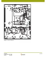
Page 14: ...EB GS2972 Evaluation Board User Guide 50283 2 May 2012 14 of 22 Figure 3 2 Layer 2 Ground ...
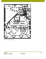
Page 15: ...EB GS2972 Evaluation Board User Guide 50283 2 May 2012 15 of 22 Figure 3 3 Layer 3 Power ...
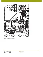
Page 16: ...EB GS2972 Evaluation Board User Guide 50283 2 May 2012 16 of 22 Figure 3 4 Layer 4 Signal 1 ...
Page 17: ...EB GS2972 Evaluation Board User Guide 50283 2 May 2012 17 of 22 Figure 3 5 Layer 5 Signal 2 ...


