EB-GS2972
Evaluation Board User Guide
50283 - 2
May 2012
8 of 22
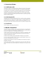
1.5 Control and Status
1.5.1 GSPI Header (JP8)
The GS2972 contains a set of internal status and configuration registers. These registers
are available to the host via the GS2972s GSPI pins. To communicate with the GS2972
and the two SRCs, a Gennum USB to GSPI dongle must be connected to the GSPI header.
A GSPI dongle is provided for communication to the GSPI interface. If you have the
EB-GS2972 and the EB-GS2970 connected together, only one GSPI dongle is required,
and can be connected to either of the boards. On the EB-GS2972, connector J29 provides
interface with the EB-GS2970.
1.5.2 JTAG Header (JP1)
This header is used for the JTAG test of the GS2972. It can also be used to communicate
with the GSPI interface of the GS4911B to program the part. To change this header to the
GS4911B GSPI interface, populate R115 and R113 with 0
Ω
, and unpopulate R114 and
R22. However, under normal conditions, the GS4911B will not need to be programmed.
1.5.3 Lock Status
LED U25 indicates the lock status of the GS2972.
1.6 Modes of Operation
The GS2972 supports four distinct modes of operation that can be set through the DIP
switch or by programming internal registers through the GSPI. These modes are: SMPTE
mode, Data-Through mode, DVB-ASI mode and Standby mode.
In SMPTE mode, the GS2972 performs all SMPTE processing features. Both SMPTE 425M
Level A and Level B formats are supported with optional conversion from Level A to
Level B for 1080p 50/60 4:2:2 10-bit.
In DVB-ASI mode, the device will perform 8b/10b encoding prior to transmission.
In Data-Through mode, all SMPTE and DVB-ASI processing is disabled. The device can
be used as a simple parallel to serial converter.
The device can also operate in a lower power Standby mode. In this mode, no signal is
generated at the output.
The DIP switches (SW6 and SW7) correspond directly to pins on the GS2972. Refer to the
GS2972 Data Sheet for a more detailed explanation of the operation of these pins in each
mode.
Summary of Contents for EB-GS2972
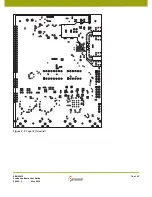
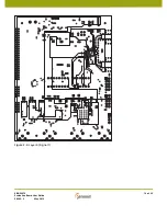
Page 14: ...EB GS2972 Evaluation Board User Guide 50283 2 May 2012 14 of 22 Figure 3 2 Layer 2 Ground ...
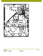
Page 15: ...EB GS2972 Evaluation Board User Guide 50283 2 May 2012 15 of 22 Figure 3 3 Layer 3 Power ...
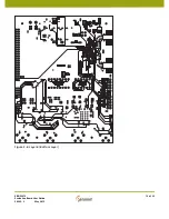
Page 16: ...EB GS2972 Evaluation Board User Guide 50283 2 May 2012 16 of 22 Figure 3 4 Layer 4 Signal 1 ...
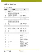
Page 17: ...EB GS2972 Evaluation Board User Guide 50283 2 May 2012 17 of 22 Figure 3 5 Layer 5 Signal 2 ...


