background image

8

ENGLISH

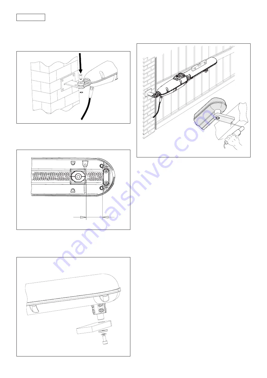
Fig. 6

Fig. 7

Fig. 8

10

2) Secure the articulated fitting of the operator to the rear

bracket by means of the supplied pins (Fig. 5).

Attention:

 before securing the operator on the rear

bracket, which has just been welded, make sure its

temperature does not damage the articulated fitting.

3) Power up the motor and move the front attachment pin

backward by about 10 mm (fig. 6).

ATTENTION: The operator can be moved by hand only if

installed on the gate in released position.

4) Fit the front bracket to the front attachment pin as shown

in Fig. 7.

5) Close the gate leaf and, holding the operator in a

perfect horizontal position, locate the front bracket

securing point on the leaf (Fig. 8).

6) Temporarily secure the front bracket on the leaf by

means of two welding points.

Note

: If the fitting cannot be secured firmly due to the

gate structure, a firm resting base on the structure is to

be created.

7) Release the operator and check manually if the gate is

free to open completely up to the mechanical stops and

if the leaf movement is regular and without any friction

whatever.

8) Completely weld the front bracket on the leaf (Fig. 8).

To do this, temporarily release the operator from the

fitting in order to avoid that welding slag damage it.

Note:

 We recommend to grease every fixing pin of the

fittings.

9) Carry out the installation of the second operator, if any,

repeating the above mentioned operations.

10) Install the enclosure and the control board keeping into

consideration the overall dimensions given in the relevant

instructions.

6. START-UP

ATTENTION: Before attempting any work on the system or on

the operator, always turn off power.

Observe points 10, 11, 12, 13, 14 of the GENERAL SAFETY

OBLIGATIONS.

Observing the instructions in Fig.3, lay the raceways and

make the electric connections of the control board to the

selected accessories.

Always separate power cables from control and safety

cables (push-button, receiver, photocells, etc...). To prevent

any electric noise whatever, use separate sheaths.
1) Program the control board according to your needs

observing the concerning instructions.

2) Switch on power to the system and check the condition

of the LEDs according to the table of the control board

instructions.

Fig. 5

Summary of Contents for Skill 01

Page 1: ...Skill 01 ...

Page 2: ... dans une atmosphère explosive la présence de gazoudefuméesinflammablesconstitueungravedangerpourlasécurité 8 LescomposantsmécaniquesdoiventrépondreauxprescriptionsdesNormes EN 12604 et EN 12605 PourlesPaysextra CEE l obtentiond unniveaudesécuritéappropriéexige nonseulementlerespectdesnormesnationales maiségalementlerespect desNormessusmentionnées 9 GENIUSn estpasresponsabledunon respectdelaBonneT...

Page 3: ... t s u r h T N a d 0 8 1 N a d 0 0 2 l e v a r T m m 5 0 3 d e e p S c e s m c 4 1 c e s m c 2 1 f a e l x a M m 2 m 5 3 C 0 2 y c n e u q e r f e s U 0 3 3 S C 0 2 s e l c y c e v i t u c e s n o C 5 1 t n e i b m a g n i t a r e p O e r u t a r e p m e t C 5 5 C 0 2 s s a l c n o i t c e t o r P 4 4 P I t h g i e w r o t a r e p O g k 4 8 s n o i s n e m i d r o t a r e p O 2 g i f e e s L E D O...

Page 4: ...In case of iron pillar carefully weld the bracket directly on the pillar Fig 4 In case of masonry pillar use the optional plate for a securing to wall or to be bolted Fig 4 Then carefully weld the bracket on the plate Table A Recommended dimensions in mm stem useful travel max dimension min dimension GENERAL RULES TO DETERMINE THEINSTALLATIONDIMENSIONS IfthedimensionsindicatedintableAcannotbereali...

Page 5: ...leaf movement is regular and without any friction whatever 8 Completely weld the front bracket on the leaf Fig 8 To do this temporarily release the operator from the fitting in order to avoid that welding slag damage it Note We recommend to grease every fixing pin of the fittings 9 Carry out the installation of the second operator if any repeating the above mentioned operations 10 Install the encl...

Page 6: ...ockwise close the cover and switch on power to the system Carry out some manoeuvres in order to check if all functions of the automated system have been correctly restored 10 MECHANICAL STOP TheSKILLoperatorisequippedwithanopeningmechanical stop Fig 10 which can be adjusted according to need Procedure for adjusting the stop position 1 Release the operator as described in point 8 2 Manually take th...

Page 7: ...sitioned If the limit switches have to be adjusted again resume from point 2 5 Re fit the lower housing 12 MAINTENANCE To ensure correct long term operation we advise you to carry out the following checks every six months 1 Check if all the safety devices in use are connected and efficient 2 Check if the anti crushing clutch is correctly set 3 Check the condition and efficiency of the earth connec...

Page 8: ...DE CONFORMITÉ DIRECTIVEEUROPÉENNE MACHINES 89 392 CEE ANNEXEII PARTIEB Fabricant GENIUS s r l Adresse Via Padre Elzi 32 24050 Grassobbio BERGAMO ITALIE Déclare d une part que l automatisme mod SKILL 01 estprévuesoitpourêtreincorporéedansunemachine soit pour être assemblée avec d autres composants ou parties en vue de former une machine selon la directiveeuropéenne machines 89 392CEE modifiée 91 36...

Reviews: