Section 6 • Schematics
November 2005
REV A
Part No. 84700
GR-12 • GR-15 • GR-20
6 - 3
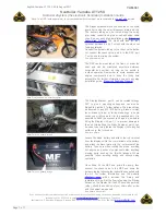
Relay Layout and ECM Pin-out Legend
ECM PIN-OUT LEGEND
Item Description
A1
Flashing beacon FB1 (output)
A2
Ground from platform controls (input)
(White wire at platform controls)
A3 Plug
A4
Power from platform controls to ECM (input)
(Red wire at platform controls)
A5
Level sensor power S7 (output)
A6
Platform up coil Y8 (output)
A7
Drive reverse coil Y5 (output)
A8
Motor controller U6, terminal 1
A9
Motor controller U6, terminal 3
A10
Overload sensor PS2 (input)
A11
Key switch to platform control (input)
A12
Platform down TS66 (input)
B1
Platform data link (high) (input)
(Blue wire at platform controls)
B2 Plug
B3
ECM ground (output)
B4 Plug
B5 Plug
B6
Platform down coil Y7 (output)
B7
Steer left coil Y4 (output)
B8
Automotive-style horn H2 (option) (output)
B9
Multi-function alarm H5 (output)
B10
Pothole limit switch (input)
B11
Drive enable power/up limit switch (input)
B12
Platform up TS66 (input)
C1
Platform data link (low) (input)
(Orange wire at platform controls)
C2
Power to ECM (input)
C3 Plug
C4 Plug
C5 Jumper
C6
Drive forward coil Y6 (output)
C7
Steer right coil Y3 (output)
C8
Parallel coil Y1
(not available on GS-1530/32 and GS-1930/32)
C9
Work light L30 (option)
C10 Jumper
C11
Level sensor signal S7 (input)
C12
Down limit switch LS66 (input)
A
12
B
C
1
1
1
12
12
12
Relay layout
a
platform overload CR27A (motor cont) (option)
b
platform overload CR27B (load sense) (option)
c
platform overload CR27C (down coil) (option)
d
auto-style horn CR5 (option)
e
power relay CR48
f
ECM diagnostic display window
g
electronic control module (ECM) U5
h
motor controller U6
a
b
c
d
e
g
f
h