


16
Genie AWP
Part No. 33424
Operator’s Manual
Fourth Edition
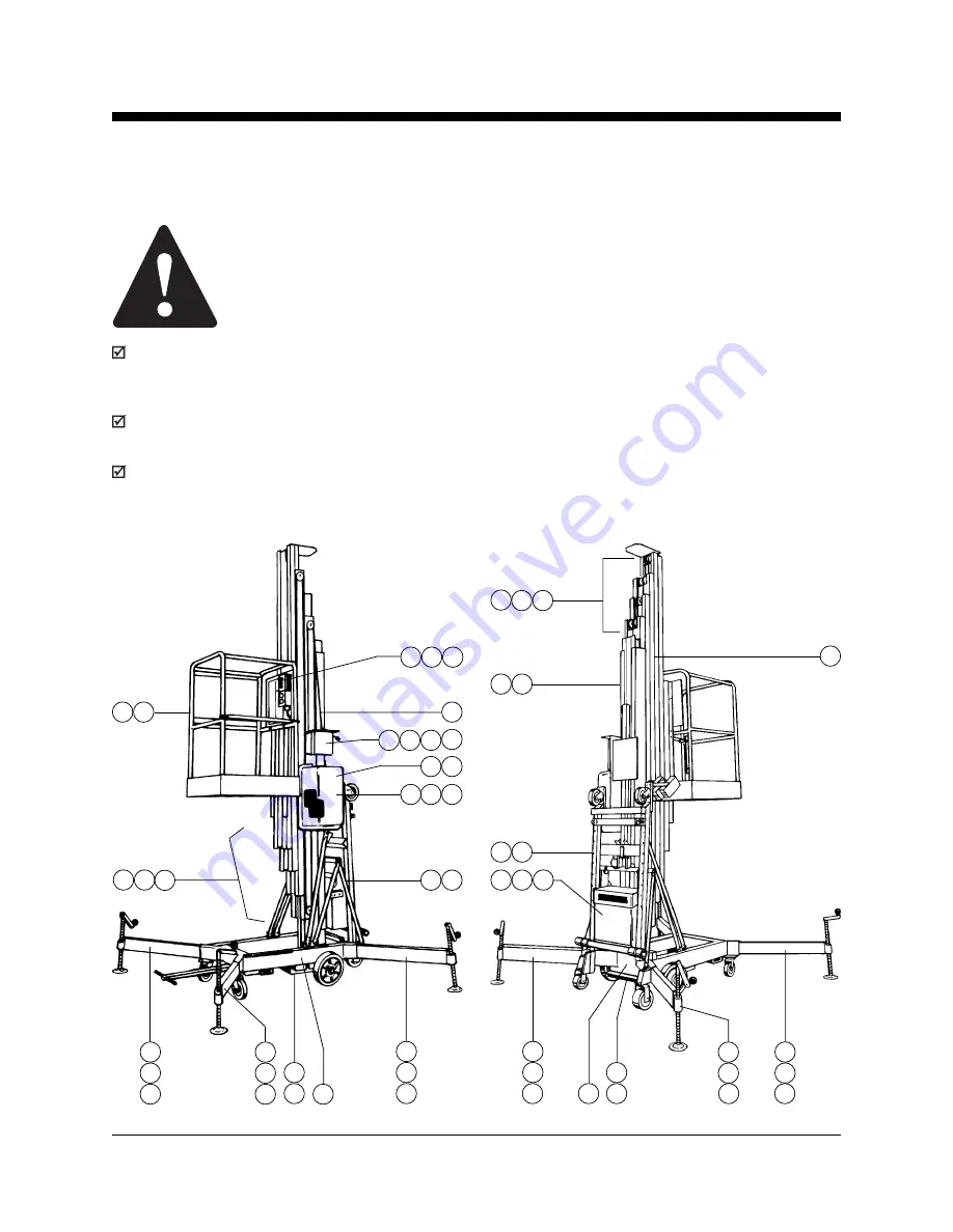
Maintenance Inspection
The Maintenance Inspection shall be
completed daily by a person trained and
qualified on the maintenance of this machine.
Immediately tag and remove from service a
damaged or malfunctioning machine.
Repair any machine damage or malfunctions
before operating machine.
7
3
1
6
7
3
1
4
3
7
1
1
10
3
7
3
7
6 11
9
6
3
2
1
3
2
6
5
4
11
3
2
7
3
7
3
6
1
7
3
1
7
3
7
8
3
7
3
3
3
7
3
7
3
7


