background image

27

DUAL BULB POWERHEAD

1

2

3

4

5

6

7

8

9

9

2

4

10

11

Item #

Description

QTY.

1

COVER, DUAL BULB

1

2

LENS

2

3

MOTOR ASSEMBLY

1

4

SOCKET,ANGLED LIGHT

2

5

TRANSFORMER,120VAC

1

6

PCB, DC CONTROLLER

1

7

POWER CORD,45”

1

8

SCR,M6-1 X 12 HWH THDF (3pk)

1

9

SCR,HHD,SLTD,TAP,#8X5/1 (3pk)

2

10

ICDM BOARD (Integrated Aladdin Models Only)

1

11

OPTICAL ENCODER ASSEMBLY

1

Specify model number when ordering parts from Genie Customer Care. 

Summary of Contents for 1035

Page 1: ...Genie Company All other trademarks are property of their rightful owners Consistent with our policy of continu ing product improvements we reserve the right to change product specifications without prior notice or obligations HomeLink is a registered trademark of Gentex Corporation Car2U is a registered trademark of Lear Corporation Patents www GenieCompany com patents 38967503545_EnglishWeb 09 20...

Page 2: ...reless Keypad 22 23 Parts 24 27 DASMA Information 28 31 Warranty 32 T 1 2 3 4 5 6 7 8 INDEX SAVE THESE INSTRUCTIONS READ AND FOLLOW ALL INSTRUCTIONS 9 FCC Part 15 21 Statement Changes or modifications not expressly approved by the party responsible for compliance could void the user s authority to operate the equipment FCC IC Statement This device complies with FCC Part 15 and Industry Canada lice...

Page 3: ...hnical support via our website customer support department or local servicing Genie dealer Model Number ______________________________ Serial Number _______________________________ 1 Bulb Models 2 Bulb Models Please take a moment to preview this manual and assembly poster to ensure that you have the proper tools and skill set to install a new garage door opener Pay particular attention to all Safe...

Page 4: ...dération IMPORTANTES CONSIGNES DE SÉCURITÉ DANGER POTENTIEL EFFET PRÉVENTION PORTE EN MOUVEMENT AVERTISSEMENT Pourrait entraîner des blessures graves voire la mort Utiliser uniquement si la porte est en vue et libre de tout obstacle Ne laisser personne se tenir dans l ouverture de la porte pendant qu elle est en mouvement Ne pas permettre aux enfants de jouer avec l opérateur de la porte Ne pas mo...

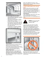
Page 5: ... of power until instructed to do so Locate the wall control button A Within sight of door B At a minimum height of 5 feet so small children cannot reach it C Away from all moving parts of the door Install the entrapment WARNING label next to the wall button or console in a prominent location Install the emergency release handle on the emergency release cord The opener must reverse when the door co...

Page 6: ...is ON the Open Close button will CLOSE the door only NOTE Constant button pressure in the CLOSE mode will override STB fault in the powerhead and close door 3 Independent Light Control Button Use this button to turn the powerhead lights ON Powerhead lighting will remain ON until this button is pressed again or a door action has been completed 4 Sure Lock Button When Sure Lock is ON and the door is...

Page 7: ...ed remote control transmitters Describes how to program remotes to sync with additional remote control devices wall consoles keypads and the powerhead NOTE The 3 programming buttons are for programming ONLY These buttons can NOT be used to operate the opener once the Required Programming section has been successfully completed Term Definitions Travel Limits Programmable setting to adjust how far d...

Page 8: ...mpany com NE PAS fixer de limites en mode batterie de secours L alimentation CA DOIT être branchée sur l ouvre porte pendant le réglage des limites pour assurer un bon fonctionnement 1 Press and hold the DOWN arrow button Long LED will light BLUE 2 Release DOWN arrow button Long LED will flash BLUE 3 Press and hold the DOWN arrow button until door is fully closed Use the UP arrow button if door cl...

Page 9: ... will flash BLUE 3 Press and hold the UP arrow button until door is fully open Use the DOWN arrow button if door opens too far Use both UP and DOWN buttons to adjust open travel as necessary Door should fully open so that door seal is even with door header Do Not adjust so much that the door will bend or buckle or stretch door spring cables backward 4 Press and release the SET PRGM button Both LED...

Page 10: ...D INVERSION AU CONTACT 1 Press and release the Wall Control button and allow the garage door to travel and stop at the DOWN limit 2 Press and release the wall control button and allow the garage door to travel and stop at the UP limit 1 With the garage door open lay a 2 X 4 board flat on the floor at the center of the door opening 2 Close the garage door using the wall control When the door contac...

Page 11: ...feet away from opener and slowly press and release the desired button on the remote two times Both opener LEDs will flash and turn off indicating the remote has been programmed 4 Press the desired remote button again The opener should run To program the same remote for other garage door openers repeat the steps above using one of the other remaining remote buttons REPEAT STEPS 1 TO 4 FOR EACH OPEN...

Page 12: ...ding codes for any requirement that you must have a permanent hard wired connection Permanent hard wired connections must be performed by a licensed electrician using proper tools and instructions AVERTISSEMENT L opérateur qui est équipé d une prise électrique mise à la terre pour votre protection est compatible uniquement avec des prises électriques mises à la terre NE PAS modifier la fiche dune ...

Page 13: ...m check as follows 1 Start the door closing 2 Pass an object through the beam The door should stop and reverse to the fully open position Door should remain stationary or move very slowly If door moves quickly CONTACT A TRAINED DOOR SYSTEM TECHNICIAN to have your door springs serviced Close the door Place the carriage in the engage position see illustration Operate door using remote or wall contro...

Page 14: ... not twisted or bound 8 Manually open door to re engage carriage to turnbuckle G Chain Belt Tension 1 4 WARNING Use extreme caution when working from a ladder or step stool or serious injury can occur When replacing light cover make sure wires are not pinched or near moving parts Use only properly rated incandescent LED or CFL light bulbs DO NOT use bulbs with a rating greater than 60 Watts Use A1...

Page 15: ...ord and manually close door 3 Make sure carriage latch is in the upright engaged position 4 Remove 2 5 16 machine screws and cap 5 Pull spring assembly out and reverse direction 6 Install cap and machine screws Emergency Release cable can now be assembled to the carriage assembly Conditions possibly requiring adjustments are 1 Doors with very stiff weather seals 2 Doors that start down STOP and re...

Page 16: ...tes interference with Safe T Beam Receiver Green LED STB modules CAN be positioned further away from the door opening if necessary to avoid sunlight but no further off the wall to maintain alignment with the Transmitter Red LED module WARNING AVERTISSEMENT CHOC ÉLECTRIQUE OUVERTURE DE COUVERTURE PEUT PROVOQUER CHOC ÉLECTRIQUE Coupez l alimentation du premier match avant de retirer le couvercle BBU...

Page 17: ...e as follows Press and hold the wall control button until door is completely closed Check for interference from adjacent Safe T Beam units See page 16 Contact Genie at 1 800 35 GENIE Door starts down then STOPS before it is closed OR Door will only open Check Safe T Beam wire connection at powerhead and at STBs See page 16 Safe T Beam system check Check if limits are properly set See pages 8 9 Adj...

Page 18: ...nt failure detected Check door spring track rollers hinges and fixtures OFF ON RED STEADY Thermal cutout DO NOT unplug unit Wait until LED clears before operating ON PURPLE STEADY ON PURPLE STEADY Component error Contact a trained door system technician OFF ON BLUE FLASHING Door will not open Check Sure Lock Sure Lock should be OFF for normal operation see page 6 ON PURPLE FLASHING ON PURPLE FLASH...

Page 19: ...s will damage the powerhead 1 Unplug powerhead from power source 2 Unplug battery backup from harness connection 3 Remove both mounting screws from rear of battery backup 4 Detach battery backup from back of opener by tilting the BBU approximately 45 degrees and lifting up towards the ceiling 5 Remove 4 screws from battery hold down bracket 6 Remove battery 7 Disconnect harness wires from the and ...

Page 20: ...SET PRGM button on the opener for two seconds The ROUND LED will turn BLUE The ROUND LED will then flash PURPLE 2 Press and hold the UP DOWN buttons at the same time until both LEDs turn off Both opener LEDs will flash and turn off indicating that all remotes have been erased 3 Press any remote button The opener should NOT run To deprogram the same remote for other garage door openers repeat the s...

Page 21: ...The default setting for the Car2U system is Button 1 Genie Manufactured Openers Button 2 LiftMaster Manufactured Openers Button 3 Wayne Dalton Manufactured Openers A Press and hold buttons 1 and 3 for 20 seconds or until all three LEDs begin to flash B Release both buttons The Car2U system is now set to the Factory Default settings NOTE Clearing the Car2U remote will remove all previously programm...

Page 22: ...f NOTE Only one PIN number can be used The keypad is now programmed with a PIN number and set up for multi opener operation Keypad is now ready to program to multiple Genie Intellicode garage door openers If LED did not blink twice and shut off please see RESETTING THE KEYPAD FACTORY DEFAULT section STEP 2B PROGRAMMINGTHE KEYPAD FOR MULTIPLE OPENERS UPTO 3 1 Place desired garage door opener 1 2 or...

Page 23: ...ed REPLACING BATTERIES Keypad MUST be mounted within sight of the garage door s at least 5 feet above floor and clear of any moving door parts Programming will not be lost during battery change 1 Remove battery cover and batteries 2 Drill a 3 32 pilot hole for the top mounting screw 3 Install included screw into pilot hole leaving 1 8 gap between the screw head and wall 4 Hook the slotted mount on...

Page 24: ...1 1 TURNBUCKLE 1 2 PIN CLEVIS 5 16 X 1 3 4 2 3 COTTER HAIRPIN 0725 DI 2 4 BOLT HH PLD 5 16 18 X 2 1 5 NUT 5 16 18 HX SERR FLG 1 6 STRAP RAIL RECT 1 7 SCR SERR HWH AB 1 4 14 4 8 BRKT HEADER RECT RAIL 1 9 SCR LAG HWH TPG 5 16 X1 2 1 3 2 Safe T Beam Set Safe T Beam sensor Safe T Beam source 1 4 x 1 1 4 Lag screw x4 Item Part Number Description Qty E 37220R Safe T Beam Set 1 1 XMTR ASSY STB 1 2 RCVR A...

Page 25: ...PLACEMENT PARTS Item Description Qty A 5 pcs Rail Assembly Complete Chain 1 5 pcs Rail Assembly Complete Belt 1 B Sprocket Support Assembly Chain 1 Sprocket Support Assembly Belt 1 C Carriage Assembly 1 D Idler Pulley 1 E Chain Assembly 7Ft 1 Belt Assembly 7Ft 1 F Door Arm Curved 1 G Door Arm Straight 1 H Strap Hanging 3 4 X 25 2 I 90 Ft Wire Spool 1 J Wall Console 1 K Wall Button 1 L Battery Back...

Page 26: ... BULB 1 2 LENS 1 3 MOTOR ASSEMBLY 1 4 SOCKET LIGHT 30 DEG ANG 1 5 TRANSFORMER 120VAC 1 6 PCBA DC CONTROLLER 1 7 POWER CORD 45 1 8 SCR M6 1 X 12 HWH THDF 3pk 1 9 SCR HHD SLTD TAP 8X5 1 3pk 2 10 Optical Encoder Assembly 1 Specify model number when ordering parts from Genie Customer Care ...

Page 27: ...OTOR ASSEMBLY 1 4 SOCKET ANGLED LIGHT 2 5 TRANSFORMER 120VAC 1 6 PCB DC CONTROLLER 1 7 POWER CORD 45 1 8 SCR M6 1 X 12 HWH THDF 3pk 1 9 SCR HHD SLTD TAP 8X5 1 3pk 2 10 ICDM BOARD Integrated Aladdin Models Only 1 11 OPTICAL ENCODER ASSEMBLY 1 Specify model number when ordering parts from Genie Customer Care ...

Page 28: ... few simple precautions can protect our family and friends from potential harm Please take a few minutes to read the following safety and maintenance tips Refer to your garage door and opener owner s manual for details specific to your garage door and automatic opener Some of the following precautions and warnings are identified with this Safety and Alert Symbol This symbol indicates a potential p...

Page 29: ...s to inspect and test your complete garage door system Make monthly inspection and testing a part of your regular routine Safety is everyone s business Make garage door and garage door opener safety automatic in your home Monthly Maintenance Checklist Garage Door Opener Reversal Test Force Setting Test Additional safety devices Garage Door Visual inspection springs rollers pulleys cables and track...

Page 30: ...y adjustment Additional Safety Devices Many garage door openers can be equipped with additional safety devices Consider adding a photo eye or edge sensor as an extra measure of safety to protect against entrapment Keep in mind that adding more safety devices will not make an old opener meet current UL Standards Perform routine maintenance steps once a month Review your owner s manual for the garag...

Page 31: ...you can operate the door by hand when doing this test You should be able to lift the door smoothly and with little resistance It should stay open around three or four feet above the floor If it does not it is out of adjustment Have it adjusted by a qualified service person Garage Door Opener Safety An Automatic Desision This important information is provided by the U S Consumer Product Safety Comm...

Page 32: ...r any other cause beyond the reasonable control of Seller and does not cover batteries use of extension cord missing or damaged parts from clearance or open box sales or repairs or maintenance to door components ALL EXPRESS AND IMPLIED WARRANTIES FOR THE PRODUCT INCLUDING BUT NOT LIMITED TO ANY IMPLIED WARRANTIES OF MERCHANTABILITY AND FITNESS FOR A PARTICULAR PURPOSE ARE LIMITED IN TIME TO THE AP...

Reviews: