32
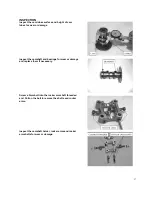
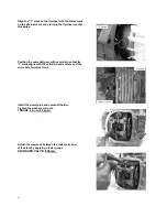
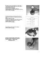
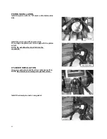
Align the “T” mark on the flywheel with the index mark
on the alternator cover by turning the flywheel counter -
clockwise.
Position the camshaft gear with cam chain so that its
“I” mark aligns with the cylinder head surface and the
circle hole forwards front.
Install the dowel pins and camshaft holder.
Tighten the washers and nuts.
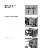
TORQUE: 20 n-m (2.0 kg-m)
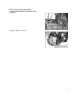
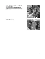
Adjust the clearance between the rocker arm and
valve stem by applying a feeler gauge.
STANDARD VALVE: 0.08 mm
Summary of Contents for XOR 125
Page 6: ...5...
Page 20: ...19 14...
Page 43: ...42 CHAPTER 4 FUEL AND LUBRICATION SYSTEM CONTENTS FUEL SWITCH CARBURETOR...
Page 64: ...63 3 Disconnect throttle cable and oil pump cable 4 Remove rear brake cable adjusting nut...
Page 91: ...90 WIRE CABLE AND BRAKE HOSE ROUTING...
Page 92: ...91 carburetor...
Page 93: ...92...
Page 94: ...93 Ignition coil Starting relay CDI HORN POWER SWITCHH...
Page 96: ...95...

