background image

21 / 32

1434 µPos

Mechanical mounting

3.1 

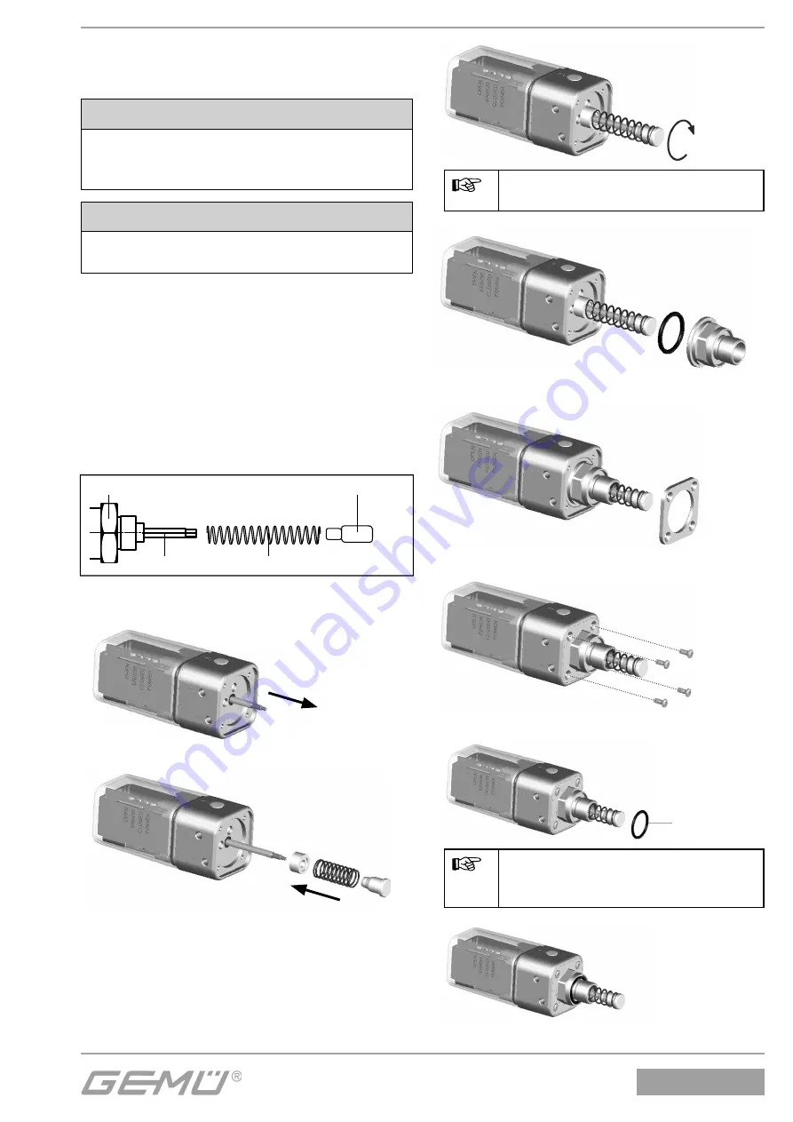
Assembling the travel sensor

CAUTION

Pretensioned spring 


ä

Damage to the device.


● Slowly release the tension in the spring.

CAUTION

Damage to the spindle surface may 
lead to failure of the tr

avel sensor!

The  travel sensor is assembled using 
a 1434S01Z... (direct mounting) and/
or 4232S01Z... (remote mounting) or 
1444000Z... (direct mounting above 
mounting bracket) mounting kit, comprising 
compression spring, operating bush, 
threaded adapter if applicable and/or 
mounting bracket. The mounting kit depends 
on the valve type.

Travel sensor

Spindle

Compression spring

Operating bush

Mounting kit

1.

2.

3.

Hold the spindle and tighten the 
operating bush hand tight.

4.

5.

6.

7.

A

Enclosed for control functions 2 
and 3, if no adapter is included:


7

O-ring 

A

8.

Summary of Contents for 1434 mPos

Page 1: ...perated linear actuators Status 07th October 2016 From version 1 1 2 1 GB INSTALLATION OPERATING AND MAINTENANCE INSTRUCTIONS Intelligenter Stellungsregler für fremdgesteuerte Linearantriebe Stand 07 10 16 Ab Version 1 1 2 1 DE ORIGINAL EINBAU UND MONTAGEANLEITUNG ...

Page 2: ...tzt werden darf Die in dieser Einbau und Montageanleitung genannten Verordnungen Normen und Richtlinien gelten nur für Deutschland Bei Einsatz des GEMÜ 1434 μPos in anderen Ländern sind die dort geltenden nationalen Regeln zu beachten Wenn es sich um harmonisierte europäische Normen Standards und Richtlinien handelt gelten diese im EG Binnenmarkt Für den Betreiber gelten zusätzlich soweit vorhande...

Page 3: ...unbedingt die elektrische Sicherheit der speisenden Geräte sicher Beachten Sie auch die Einhaltung der elektrischen Daten Die Nichtbeachtung der Sicherheitshinweise kann sowohl eine Gefährdung für Personen als auch für die Umwelt und den GEMÜ 1434 μPos zur Folge haben Die Nichtbeachtung der Sicherheitshinweise kann zum Verlust jeglicher Schadensersatzansprüche führen Gesetzliche Bestimmungen einha...

Page 4: ...s Eindringen von Flüssigkeiten geschützt Bei speziellen Erfordernissen kann die Abdichtung aber noch optimiert werden um die Schutzart zu erhöhen Dazu sind die beiden integrierten Entlüftungsventile an den Anschlüssen 3 und 4 zu entfernen und auf eine Pneumatikverschraubung umzurüsten Standardmäßige M5 Pneumatikverschraubungen können mithilfe eines separat erhältlichen Gewindeadapters genutzt werd...

Page 5: ...ehrtheit Aus den Versandpapieren geht der Lieferumfang hervor Stellen Sie anhand der Bestellnummern fest ob die Ware hinsichtlich der Ausführung und des Umfangs bestellgemäß geliefert wurde Wird der Stellungsregler GEMÜ 1434 μPos mit einem Ventil als Kompletteinheit bestellt so sind diese Teile sowie das dazugehörige Zubehör bereits komplett montiert und werkseitig voreingestellt Der GEMÜ Stellung...

Page 6: ...nbausatz 1434S01Z direkter Anbau bzw 4232S01Z externer Anbau oder 1444000Z direkter Anbau über Befestigungswinkel bestehend aus Druckfeder Betätigungsspindel evtl Gewindeadapter und oder Befestigungswinkel komplettiert Der Anbausatz ist ventilspezifisch Weggeber Spindel Druckfeder Betätigungsspindel Anbausatz 1 2 3 Spindel festhalten und Betätigungs spindel handfest anziehen 4 5 6 7 A Bei Steuerfun...

Page 7: ... Anbau des Stellungsreglers 1 2 3 Ventil mit Stellungsregler Weggeber komplettieren siehe Kapitel 3 1 Komplettierung des Weggebers l Stellungsregler 1 auf Antrieb 3 bzw Adapter E aufsetzen und mit einem geeigneten Gabelschlüssel SW 20 SW 24 am Weggeber 2 fixieren Die Gewindegröße ist abhängig von dem Ventil auf das der Stellungsregler montiert wird Der Regler darf nicht durch drehen des Gehäuses be...

Page 8: ...7 am Weggeber 4 fixieren SW27 3 4 Weggeber und Antrieb Weggeber auf Antrieb montiert 3 4 Anbau des Stellungsreglers mit Befestigungswinkel Der Anbau des Stellungsreglers mit Befestigungswinkel wird bei Ventilen angewandt die eine größere Stel lungsänderung verrichten als der integrierte Weggeber des Stellungs reglers erfassen kann 4 3 1 5 Ventil mit Befestigungswinkel Weggeber komplettieren siehe K...

Page 9: ...it externem Weggeber X3 wird nur in Kombination mit externem Wegmessystem benötigt Anschluss Pin Signalname X3 A kodiert M12 Dose 1 UP Ausgang Potentiometer Versorgungsspannung 2 UP Eingang Potentiometerschleiferspannung 3 UP Ausgang Potentiometer Versorgungsspannung 4 n c 5 n c Reglergehäuse erden über Befestigungswinkel Bei Montage des Potentiometers ESD Schutzmaßnahmen vornehmen VORSICHT Kabelb...

Page 10: ...ERROR b POWER l GND 24V DC 4 3 1 2 5 2 Initialisierungsspannung deaktivieren LED Symbol LED Symbol OPEN I CLOSED I ERROR m POWER l GND 24V DC 4 3 1 2 5 3 Die automatische Initialisierung wird durchgeführt LED Symbol LED Symbol OPEN I CLOSED I ERROR m POWER l Initialisierung 6 3 Inbetriebnahme 1 Analogen Sollwert 4 20 mA 0 20 mA 0 10 V vorgeben LED Symbol LED Symbol OPEN m CLOSED m ERROR m POWER l ...

Page 11: ...fährt in Richtung ZU m m I l Regler in Initialisierungsphase I m I l Sollwert 20 5 mA 10 25 V Fehler Nr 1 I b m l Sollwert 3 5 mA Fehler Nr 2 m b I l Regler nicht initialisiert Fehler Nr 3 I b I l Regler nicht kalibriert Fehler Nr 4 l l l I Gerätefehler Fehler Nr 5 m b m l Regler arbeitet mit geringer Güte Warnung Nr 1 Z l Legende LED Zustand Blinkfrequenz m LED aus l LED an Z LED blinkt kurz auf ...

Page 12: ...des Prozessventils b Leichtgängigkeit des Prozessventils c schwankenden Mediumsdruck während Initialisierung falls möglich Mediumsdruck absperren 9 Entsorgung l Alle Teile entsprechend den Entsorgungsvorschriften Umweltschutzbestimmungen entsorgen l Auf Restanhaftungen und Ausgasung von eindiffundierten Medien achten 10 Rücksendung l Stellungsregler reinigen l Rücksendeerklärung bei GEMÜ anfordern...

Page 13: ...r Anbau mm X1 3 4 X 95 20 13 6 42 55 6 SW 20 bei Anbausatz M12 x1 x 9 mm SW 24 bei Anbausatz M16 x1 x 11 mm Befestigungswinkel mm 54 81 2 Externer Anbau mm 20 42 6 11 M20x1 5 SW27 SW24 11 2 21 35 Ø 6 5 158 52 31 7 13 6 95 X1 X3 SW24 ...

Page 14: ...t u Signalanschlüsse Installation Betriebsanleitung beachten Reglerangaben Regelabweichung 1 Werkseinstellung 0 1 einstellbar 2 0 voreingestellt K Nr 2442 5 0 voreingestellt K Nr 2443 Initialisierung automatisch über 24 V DC Signal Dichtschließfunktion ZU W 0 5 AUF W 99 5 Anzeigeelemente Status Anzeige 4 gut sichtbare LED s Störeinflüsse auf Sollwertsignal können Regelaktivitäten beeinflussen Wegm...

Page 15: ...ngsregler GEMÜ 1434 S01 Z Anbausatz für Weggeber GEMÜ 1219 Anschluss Dose Benötigte Teile für externen Anbau GEMÜ 1434 S01 Stellungsregler GEMÜ 4232 S01 Z Anbausatz für Weggeber GEMÜ 4232 000 Z 4001 Weggeber GEMÜ 1434 000 Z MP Befestigungswinkel GEMÜ 1219 Anschluss Dose Anschluss Pneumatisch Code Zuluft Ausgang über M5 Anschlussgewinde 1 Zuluft Ausgang über Schnellsteckverbinder winklig 4 mm 2 Zul...

Page 16: ...a GEMÜ Gebr Müller Apparatebau GmbH Co KG Fritz Müller Straße 6 8 D 74653 Ingelfingen erklären dass das unten aufgeführte Produkt der folgenden Richtlinie entspricht EMV Richtlinie 2014 30 EU Produkt GEMÜ 1434 Joachim Brien Leiter Bereich Technik Ingelfingen Criesbach September 2016 ...

Page 17: ...n and commissioning by trained personnel Operation according to these installation operating and maintenance instructions Recommended maintenance All rights including copyright and industrial property rights are expressly reserved The GEMÜ 1434 μPos must be used in accordance with these directions All information in these installation operating and maintenance instructions regarding operation serv...

Page 18: ...ensure that the electrical values are correct If the safety information is disregarded persons the environment and the GEMÜ 1434 μPos may be endangered Furthermore failure to observe the safety information may lead to a complete loss of claims rights Adhere to legal regulations 1 3 Correct use The GEMÜ 1434 μPos is suitable for use in specific fixed plant as defined in the data sheet In order to e...

Page 19: ...he GEMÜ 1434 μPos is protected against the penetration of liquid as standard In order to meet special requirements however the sealing can be further optimized to increase the protection class To do this remove the two integrated venting valves at connections 3 and 4 and convert them to a pneumatic connection As standard M5 pneumatic connections can be used by means of a threaded adapter which is ...

Page 20: ...s are present and check for any damage immediately upon receipt The scope of delivery is apparent from the dispatch documents Use the order numbers to check whether the type and scope has been delivered as ordered If the GEMÜ 1434 μPos positioner is ordered as a complete unit with a valve these parts as well as the accessories are supplied fully assembled and preset at the factory The GEMÜ positio...

Page 21: ...434S01Z direct mounting and or 4232S01Z remote mounting or 1444000Z direct mounting above mounting bracket mounting kit comprising compression spring operating bush threaded adapter if applicable and or mounting bracket The mounting kit depends on the valve type Travel sensor Spindle Compression spring Operating bush Mounting kit 1 2 3 Hold the spindle and tighten the operating bush hand tight 4 5...

Page 22: ...rture until it stops and tighten 3 2 Mounting the positioner 1 2 3 Valve with positioner Assemble the travel sensor see chapter 3 1 Assembling the travel sensor l Place the positioner 1 on actuator 3 or adapter E and fix it to the travel sensor 2 using a suitable open end wrench SW 20 SW 24 The thread size depends on the valve to which the positioner is mounted The positioner must not be fixed by tu...

Page 23: ... a suitable open end wrench SW27 SW27 3 4 Travel sensor and actuator Travel sensor mounted on actuator 3 4 Mounting the positioner using a mounting bracket The positioner is mounted with a mounting bracket when valves are used which have larger position changes than the integrated travel sensor on the positioner can detect 4 3 1 5 Valve with mounting bracket Assemble the travel sensor see chapter ...

Page 24: ...h external travel sensor X3 is only required in combination with an external travel sensor system Connection Pin Signal name X3 A coded M12 socket 1 UP output potentiometer supply voltage 2 UP input potentiometer wiper voltage 3 UP output potentiometer supply voltage 4 n c 5 n c Earth the positioner housing using mounting bracket Take ESD protective measures when mounting the potentiometer CAUTION...

Page 25: ...ER l GND 24V DC 4 3 1 2 5 2 Deactivate initialisation power supply LED Symbol LED Symbol OPEN I CLOSED I ERROR m POWER l GND 24V DC 4 3 1 2 5 3 Automatic initialisation is carried out LED Symbol LED Symbol OPEN I CLOSED I ERROR m POWER l Initialisation 6 3 Commissioning 1 Specify an analogue set value of 4 20 mA 0 20 mA 0 10 V LED Symbol LED Symbol OPEN m CLOSED m ERROR m POWER l GND 4 3 1 2 5 4 2...

Page 26: ...ve moves in CLOSED direction m m I l Positioner in initialisation phase I m I l Set value 20 5 mA 10 25 V Error no 1 I b m l Set value 3 5 mA Error no 2 m b I l Positioner not initialised Error no 3 I b I l Positioner not calibrated Error no 4 l l l I Device error Error no 5 m b m l Positioner works with lower quality Warning no 1 Z l Key LED conditions Flashing frequency m LED off l LED on Z LED ...

Page 27: ...ocess valve c Unstable medium pressure during initialisation if possible turn off media pressure 9 Disposal l All valve parts must be disposed of according to relevant local or national disposal regulations environmental protection laws l Pay attention to adhered residual material and gas diffusion from penetrated media 10 Returns l Clean the positioner l Request a return delivery note from GEMÜ l...

Page 28: ...mounting mm X1 3 4 X 95 20 13 6 42 55 6 SW 20 for mounting kit M12 x1 x 9 mm SW 24 for mounting kit M16 x1 x 11 mm Mounting bracket mm 54 81 2 Remote mounting mm 20 42 6 11 M20x1 5 SW27 SW24 11 2 21 35 Ø 6 5 158 52 31 7 13 6 95 X1 X3 SW24 ...

Page 29: ...24 V DC signal Close tight function CLOSED W 0 5 OPEN W 99 5 Display elements Status display 4 visible LEDs Interferences on set value signal may influence control activities Operating conditions Ambient temperature 0 to 60 C Storage temperature 10 to 60 C Control medium Quality classes to DIN ISO 8573 1 Dust content Class 3 max particle size 5 µm max particle density 5 mg m Pressure dew point Cla...

Page 30: ...value input B 0 10 V set value input C Material Code Aluminium base PP cover 14 Stainless steel base PP cover 07 Required parts for remote mounting GEMÜ 1434 S01 positioner GEMÜ 4232 S01 Z travel sensor mounting kit GEMÜ 4232 000 Z 4001 travel sensor GEMÜ 1434 000 Z MP mounting bracket GEMÜ 1219 connector socket Option Code Without 00 4 20 mA actual value output A0 0 20 mA actual value output B0 0...

Page 31: ...we GEMÜ Gebr Müller Apparatebau GmbH Co KG Fritz Müller Straße 6 8 D 74653 Ingelfingen declare that the product listed below complies with the following directive EMC Directive 2014 30 EU Product GEMÜ 1434 Joachim Brien Head of Technical Department Ingelfingen Criesbach September 2016 ...

Page 32: ...n Subject to alteration 10 2016 V1 1 2 1 88273371 GEMÜ Gebr Müller Apparatebau GmbH Co KG Fritz Müller Str 6 8 D 74653 Ingelfingen Criesbach Telefon 49 0 7940 123 0 Telefax 49 0 7940 123 192 info gemue de www gemu group com ...

Reviews: