


917334/BP0310
25
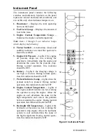
10. Keyswitch
–
In a clockwise rotation, these positions are:
OFF Position –
With the key vertical, power from the battery is disconnected
to the controls and instrument panel electrical circuits. This is the only posi-
tion the key can be inserted or removed from the keyswitch.
ON (or Run) Position –
With the key turned one position clockwise from
vertical, power from the battery is supplied to all control and instrument panel
electrical circuits.
START Position –
With the key turned fully clockwise, the electric starter
energizes, start the engine. Release the key to the RUN position after the
engine starts.
Note: The engine cannot be started unless the operator is sitting in the seat and
the restraint bar is lowered.
11. Parking Brake Switch –
Used to manually apply the parking brake. The red
indicator on the switch lights when the parking brake is applied.
12. Light Switch –
Controls all the lights on the loader. Symbols denote the four
positions of the light switch. In a clockwise direction these are:
• OFF
• Tail Lights ON
• Front Work Lights with Tail Lights ON
• both Front and Rear Work Lights
For the lights to function, the keyswitch must be in the RUN position.
13. Circuit Breakers –
Four circuit breakers on the instrument panel protect the
loader’s electrical circuits.
Important: Do not attempt to defeat the circuit protection by jumping across a
circuit breaker or by using a higher amperage circuit breaker.
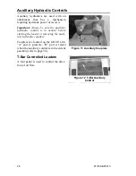
14.
Accessory Outlet –
12-volt DC power outlet.
Summary of Contents for SL3640E
Page 8: ...4 917334 BP0310 Notes...
Page 20: ...16 917334 BP0310 Notes...
Page 34: ...30 917334 BP0310 Notes...
Page 44: ...40 917334 BP0310 Notes...
Page 60: ...56 917334 BP0310 Notes...
Page 70: ...66 917334 BP0310 Notes...
Page 72: ...68 917334 BP0310 Maintenance Log Date Hours Service Procedure...
Page 73: ...917334 BP0310 69 Maintenance Log Date Hours Service Procedure...
Page 74: ...70 917334 BP0310 Notes...
Page 82: ...78 917334 BP0310 Notes...