


page | 97
Advanced Operation
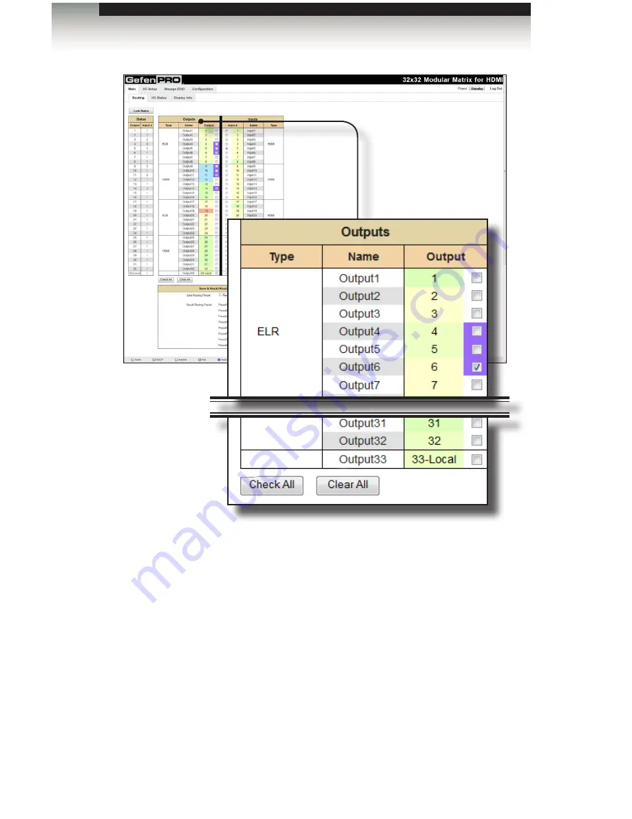
Web Interface
Output
Click to place a check mark in the box and select the desired output. Multiple
outputs can be selected. This includes the local A/V output (33-Local).
Name
Displays the current name of the output.
Type
Indicates the type of card that is installed for the listed outputs.
Check All
Click this button to select all outputs.
Clear All
Click this button to clear (deselect) all selected outputs


