GECMA CHALLENGER 15 Inch Operating And Installation Instructions Download Page 29


GECMA COMPONENTS GMBH 


WWW.GECMA.COM


TEL. +49 2237 6996-0 

FAX. -99

MANUAL CHALL 15_18 EN REV.1.3.NEX.DOC 

 31.01.07 

 A.J 

   29


Fine tuning 

Before turning on the CHALLENGER 15/18-FMO, it is necessary to tune the data transmission to the 

length of cable used. For this purpose three DIP switches S5 to S7 are used. All three switches 
must be set in the same position to work correctly. For cable runs over 275m, several additional 

jumpers on the TCV2 are already set from GECMA Components  (further details see “Design of 

the TCV2 data transmission card“). 
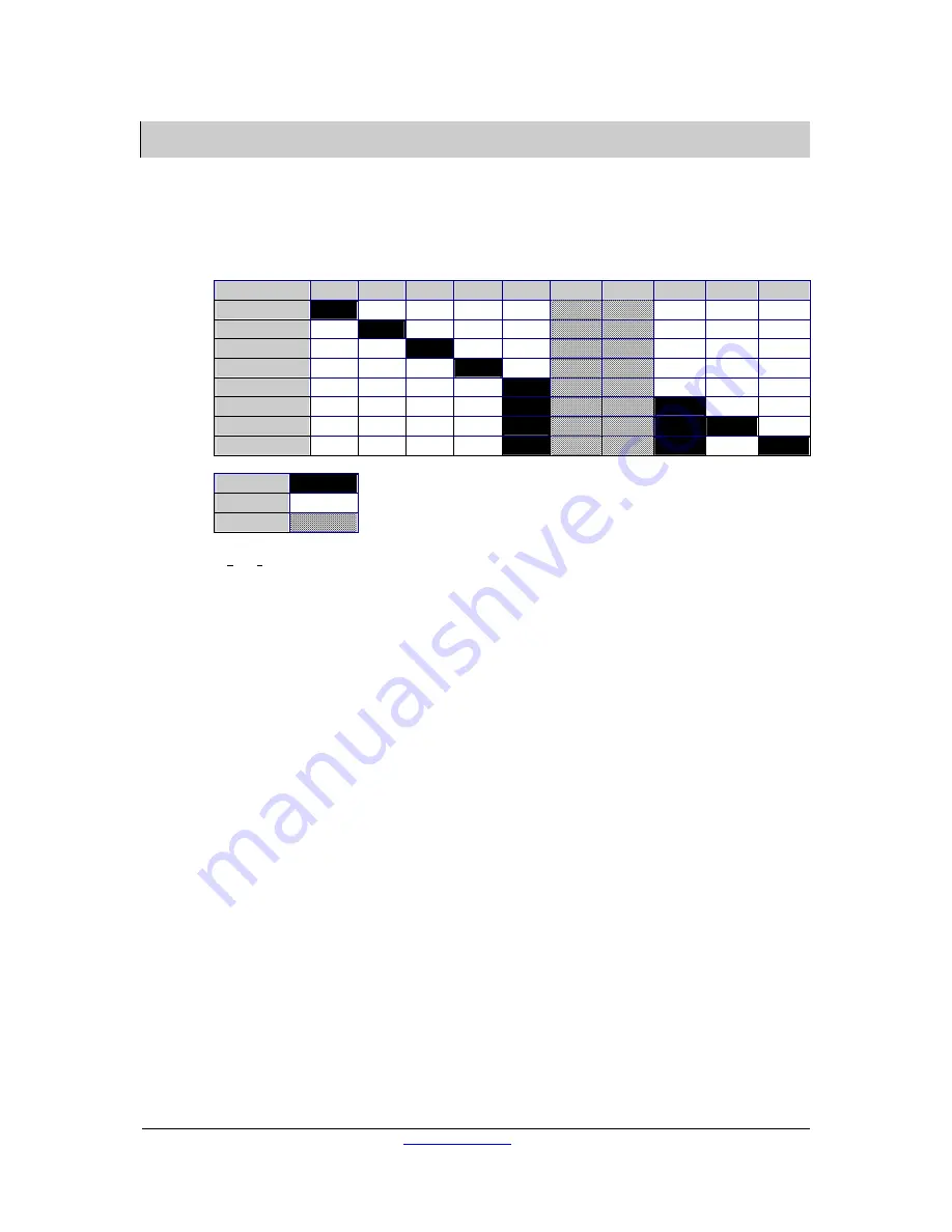
S5, S6, S7 

10 

30 –   75m   


75 – 125m 


125 – 175m 


175 – 300m 


275 – 325m 


325 – 375m 


375 – 450m 


450 – 500m 


ON 


OFF 


FT 


FT: Fine Tuning, the grey, hatched “switches“ 6 and 7 can be connected to all switch positions: 

they are used to fine tune the picture. 

Turn on the terminal and the PC and check that the keyboard and mouse are working properly. 

To tune the picture quality, open a program with a lot of fine detail on it, such as Windows 

Explorer. Remember that best picture quality can only be achieved when working in the same 

resolution as the CHALLENGER 15 (1024 x 768) and CHALLENGER 18 (1280 x 1024). This is due to 
the LCD used, as this only provides a perfectly sharp image at these resolutions. If you select a 

lower resolution, the internal logic automatically interpolates the signal to a resolution of 1024 x 

768 or 1280 x 1024. (However, if this is not an integer relationship, the picture will not look right.) 

The ideal refresh rate for the terminal should be around 60 Hz, but can be higher. 

The linear tuning is performed first using the trimming potentiometers on the rear of the 
CHALLENGER. The 

Focus potentiometer adjusts the sharpness of the picture, the Brightness 

potentiometer its brightness. Turning the controls to the left sharpens or increases picture 

brightness respectively, while turning to the right has the opposite effect in each case.   

Start by making the picture darker and out of focus. Now increase the Brightness  to half the 

required value and then sharpen the image using the  Focus control. Adjust slightly as required. 

Now carry out an auto adjust (see Operation and calibration of the display). If the picture is not 

right, set the brightness and contrast to around 25% in the OCD menu and adjust the picture 

using the Brightness and Focus controls on the display.  


At distances of more than 275m, line compensation may be necessary in order to achieve 
satisfactory picture quality. Use DIP switch blocks S8 to S13 and an appropriate test picture (e.g. 

längenabgleich.bmp) to carry out line compensation.  

Summary of Contents for CHALLENGER 15 Inch

Page 1: ...GECMA COMPONENTS GMBH WWW GECMA COM TEL 49 2237 6996 0 FAX 99 MANUAL CHALL 15_18 EN REV 1 3 NEX DOC 31 01 07 A J 1 OperatingandInstallationInstructions RemotePCTerminals CHALLENGER15 CHALLENGER18...

Page 2: ...ons or suggestions please contact your local representative or us directly Gecma Components GmbH Gecma International Ltd Heisenbergstra e 26 40 Meridian House Roe Street D 50169 Kerpen Congleton CW12...

Page 3: ...e may collect Please ensure that precautions have been taken to remove all traces of substances that may represent a health risk before returning the device Costs of disposal of materials or injury of...

Page 4: ...use module 14 Design of the CHALLENGER TB trackball module 15 Design of the CHALLENGER MTD 16 Design of the TCV2 data transmission card 17 Design of the PSU2 power supply unit 19 Design of the 19 rack...

Page 5: ...board and mouse tracker ball Power for the CHALLENGER 15 18 FMO display module is supplied by the 15 PSU or 18 PSU power supply unit The following variants are available Device Version CHALLENGER 15 F...

Page 6: ...1024 pixels True Colour 32 bit Operating principle The VGA screen data and keyboard and mouse tracker ball data are fed into the TCV2 where they are combined and converted into conditioned signals Th...

Page 7: ...n Temperature 0 C 50 C The Input Voltage is connected as the following table to the Terminals labelled INPUT The supply with Input Voltage for several modules is achieved by connecting them in paralle...

Page 8: ...odised aluminium Dimensions 417 x 340 5 x 70 mm w x h x d Weight 12 kg Power supply 15 PSU The connections are detailed in the following table Preferred cable No Terminal block K1 Connection 1 Not use...

Page 9: ...air a blue 10 4 Twisted pair b Preferred cable No Terminal block K4 Connection 1 1 Keyboard pointing device data a 2 2 Keyboard pointing device data b 3 3 GND 4 4 Backlight control 5 5 GND 6 6 GND 7 7...

Page 10: ...te Anodised aluminium Dimensions 505 9 x 427 7 x 80 mm w x h x d Weight 16 kg Power supply 18 PSU The connections are detailed in the following table Preferred cable No Terminal block K1 Connection 1...

Page 11: ...air a blue 10 4 Twisted pair b Preferred cable No Terminal block K4 Connection 1 1 Keyboard pointing device data a 2 2 Keyboard pointing device data b 3 3 GND 4 4 Backlight control 5 5 GND 6 6 GND 7 7...

Page 12: ...ollowing variants are possible CHALLENGER KB Trackball or Mouse CHALLENGER KMU CHALLENGER KB 2D Trackball or Mouse and Trackball or Mouse and Scanner CHALLENGER KMU 2D Trackball or Mouse and Scanner F...

Page 13: ...evice power supply 0V 11 Ext pointing device 5V 12 Ext pointing device 0V 13 Ext pointing device data 14 Ext pointing device clock 15 Not used 16 Not used 11 17 Deactivate keyboard mouse OPTION 13 18...

Page 14: ...ors much like those used in Notebook PCs For mechanical details of the CHALLENGER M module please refer to the drawings in the appendix Technical data Component CHALLENGER M Description Panel mounted...

Page 15: ...CHALLENGER KB For mechanical details of the CHALLENGER TB module please refer to the drawings in the appendix Technical data Component CHALLENGER TB Description Trackball with 55mm ball Power supply f...

Page 16: ...ical data Component CHALLENGER MTD Housing Anodised aluminium Ingress protection IP30 Power supply from display unit Anschl sse K11 18pole Phoenix socket K12 3pole Phoenix socket Dimensions 160 x 37 x...

Page 17: ...inal in the remote area using a four pair data cable The option to enable disable the terminal and also the local keyboard and mouse is possible using the digital inputs 14D and 14Z 14Z 14D Status H H...

Page 18: ...pply 12V 2Z 4D Power supply 0V 4D 4Z Power supply 0V 4Z 6D Power supply 12V 6D 6Z Power supply 12V 6Z 8D Power supply 5V 8D 8Z Power supply 5V 8Z 10D Power supply 0V 10D 10Z Power supply 0V 10Z 12D Po...

Page 19: ...r supply for TCV2 and TCS1 Component CHALLENGER PSU2 Housing 19 Euro card 3U 8HP Power supply 100 240VAC 3 15 AT Weight 0 65 kg Connector pins ST1 Connection 2D 5V 2Z 5V 4D GND 4Z GND 6D 5V 6Z 5V 8D G...

Page 20: ...All you need do is provide the power and plug in the data cable 10 pole Phoenix socket When installing more than one 19 rack into a 19 rack cabinet a minimum of 1U space must be left between each rac...

Page 21: ...r the brightness of the background lighting is reduced by 50 As soon as the keyboard mouse is used again the brightness automatically increases back to its normal level This function is implemented in...

Page 22: ...tails of the exact mounting arrangement please refer to the drawings in the appendix All housing nuts and fixing brackets must be tightened evenly If you have ordered the panel mounted module make sur...

Page 23: ...the power cable 100 240 V AC through the M25 cable gland in the STF or EBF stands to the 15 PSU or 18 PSU Terminate the power cable like the chapter Design of the 15 PSU 18 PSU and the drawings in the...

Page 24: ...Installing the local area Components Install the Rack 84 2 19 sub rack into your 19 rack cabinet or place the Rack 42 2 desktop rack on a suitable surface Connect the VGA Keyboard and Mouse cable sup...

Page 25: ...U to terminal K1 K2 and K3 on the CHALLENGER FMO The cable must be no more than 10 m length when the cable cross section is 1mm CHALLENGER 15 Display Preferred cable No Terminal Supply circuit 15 PSU...

Page 26: ...2 V 16 Preferred cable No Terminal Supply circuit 18 PSU Terminal block K2 CHALLENGER 18 FMO Cable2 1 OUTPUT 2 V 1 Cable2 2 OUTPUT 2 V 2 3 Preferred cable No Terminal Supply circuit 18 PSU Terminal bl...

Page 27: ...4 5 5 5 6 6 6 7 7 7 8 8 8 9 9 9 10 10 10 11 brown red 12 white blue 13 yellow green 14 green white 15 16 11 17 7 13 18 3 12 1 6 14 2 5 15 3 4 Connect the data cable twisted pair directly to the TCV2...

Page 28: ...dditional units VGA out VGA monitor To desktop keyboard PS 2 keyboard To desktop mouse PS 2 mouse Connect a mains cable to the IEC connector on the rear of the desktop housing If you ordered a rack th...

Page 29: ...ides a perfectly sharp image at these resolutions If you select a lower resolution the internal logic automatically interpolates the signal to a resolution of 1024 x 768 or 1280 x 1024 However if this...

Page 30: ...his would increase the propagation time for the colour red by 1ns If you look at the test picture you will see that the red colour has moved fractionally to the right If all DIP switches are in their...

Page 31: ...he other colours increased 4 The DIP switches are used to increase the times for the colours by between 0ns and 15ns so that the vertical shift comes as close as possible to the reference colour How t...

Page 32: ...the keyboard CHALLENGER KB To activate the four arrow keys on the keyboard that are used to control the OSD the key combination Ctrl OSD must be entered In other words the Ctrl key and the keys O S a...

Page 33: ...option allows the connection of an intrinscially safe video signal that can be displayed on the display in full screen mode or as a picture in picture mode 5 BCS Barcode Scanner Input With this option...

Page 34: ...0 x 525 x 200 mm and 261 x 626 x 78 mm h x b x t Material Stainless Steel 1 4301 Finish Stainless Steel ground to hygienic standards Ingress protection IP66 NEMA 4X Weight 21 kg Component CHALLENGER 1...

Page 35: ......

Page 36: ......

Page 37: ......

Page 38: ......

Page 39: ......

Page 40: ......

Page 41: ......

Page 42: ......

Page 43: ......

Page 44: ......

Page 45: ......

Page 46: ......

Page 47: ......

Page 48: ......

Page 49: ......

Page 50: ......

Reviews: