13
Step 3
Tighten the set screw of the timing wheel
using a 1.5mm allen key so it is secured at
the base of the groove in the shaft (i.e there
should be a 3mm distance between the top
of the stepper motor shaft and the stepper
gear).
Ensure that the set screw is tight. GearRev
recommends the application of thread lock
on the set screws.
Step 4
Repeat steps for the 2 remaining axis step
-
per motors.
Step 5
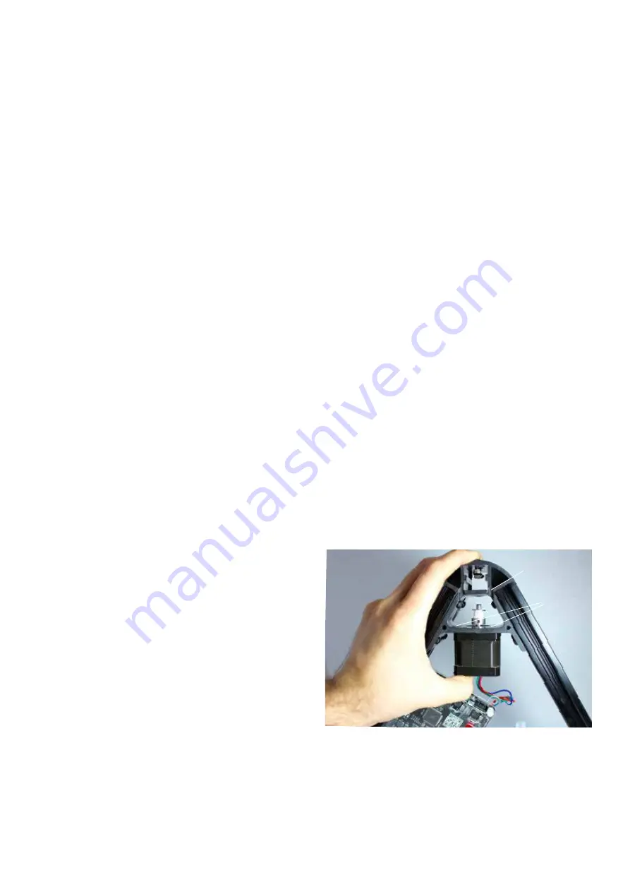
Attach stepper motor to the bottom vertex
with the wires facing down.
To start, position the stepper motor in the
vertex as seen in figure 2.2.
Figure 2.2
groove for
Allen key
screw in each
corner
Summary of Contents for Kinematics
Page 1: ...KINEMATICS 3D PRINTER MANUAL ...
Page 2: ......
Page 3: ...3 ...


