“energized”. However, in this case, the valve can
no more be operated electrically in the usual way.
5.6 INJECTION INTERSTAGE GAS COOLER (only
in two-stage comressors)
In two-stage compressors, an injection interstage
gas cooler may have been provided between the
LP-discharge connection and the HP-suction
connection. This cooler cools the gas compressed
by the LP-cylinders down to 5 to 6 K above the
saturation temperature corresponding to the
intermediate pressure.
The interstage cooler consists of an amply
dimensioned connecting tube, into which, on the
LP-discharge side, liquid refrigerant is injected.
This injection takes place either direct on the
interstage gas cooler or via a separate injection
liquid cooler. Due to the evaporation of this
liquids, the temperature of the gas to be sucked
by the HP-cylinders is reduced. The amount of
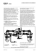
liquid is controlled by a thermostatic expansion
valve, whose temperature bulb must be clamped
externally against the HP-suction line of the
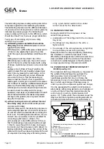
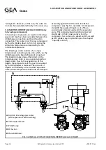
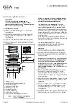
compressor (see fig. 5.4, overleaf). At compressor
standstill the supply of liquid is cut off by a
solenoid valve located upstream the expansion
valve. This solenoid valve should be connected
electrically so that it opens only when the
compressor has come up to speed and LP- as well
as HP-cylinders are in operation (see the chapter
“Capacity control”).
FIG. 5.4 INSTALLATION OF INJECTION INTERSTAGE GAS COOLER
A
Injection interstage gas cooler
(with expansion valve assembly)
B
From liquid receiver
C
LP-Discharge
D
HP-Suction
E!
Place bulb here!
Refrigeration Division
Grasso
5. DISCRIPTION AND OPERATION OF ACCESSORIES
Page 5.6
Refrigeration Compressors Series RC9
v002.97.10.en

