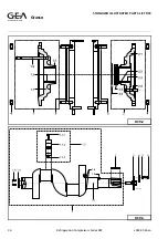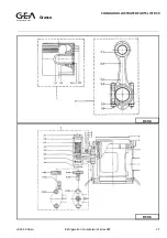
b) Remove the cylinder head cover.
CAUTION!
The nuts on the long studs must be
unscrewed last, thus enabling the buffer
spring fitted under the cover to extend before
the cover is released entirely.
c) Remove buffer spring.
d) Lift the complete discharge valve out of the
cylinder liner.
e) Remove the suction valve ring and sinusoidal
spring, which are loose on the collar of the
cylinder liner.
f) Unscrew and disassemble the discharge valve.
g) Clean all valve parts and check them for break
or damage
MIND! If it appears that valve parts are broken,
also the cylinder liner and piston of the relevant
cylinder must be checked for damage.
The
valve rings
and
valve seats
must be
undamaged; even the slightest damage may
easily cause breakage. Slightly damaged seat
edges may be trued up by grinding them on a
smooth plate or glass using a fine honing paste.
Heavily damaged or chipped-off seat edges can
no more be repaired; in such a case a new valve
must be fitted.
Valve ring and/or seat should be replaced also
when, due to wear, the total score of valve ring
and seat is over 0.2 mm.
The
sinusoidal springs
must also be
undamaged and must have sufficient slack
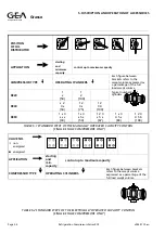
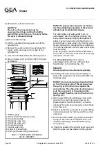
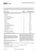
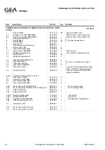
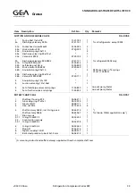
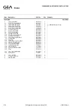
height (refer to the table in fig. 9.1).
REMARK!
All valve parts can be obtained separately.
h) Carefully clean all valve parts and slightly oil
them with compressor oil; then reassemble the
discharge valve.
MIND! The sinusoidal springs should be fitted
so that the convex side of the springs where
the spring profile is flat, bears against the
stroke limitor. The other side of which approx
only the outer point of the spring profile
bears, should therefore rest on the valve ring
(see fig. 9.1).
j) After reassembling the discharge valve, check
whether the valve ring and springs can be
pressed against the stroke limitor, and when
released, the valve ring is properly pressed back
on to their seat.
k) Check whether the push pins of the valve lifting
mechanism project 2.2 mm beyond the suction
valve seat.
l) Place the suction valve ring, and the sinusoidal
spring on the collar of the cylinder liner, and
install the discharge valve and buffer spring
into position.
m) Check the gasket of the cylinder head cover and
slide the cover over the studs onto the cylinder
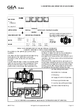
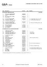
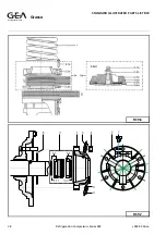
FIG.9.1 SUCTION AND DISCHARGE
VALVE ASSEMBLY
1. Buffer spring
2. Stroke limitor (discharge valve)
3. Sinusoidal springs
4. Discharge valve ring
5. Discharge valve seat
6. Sinusoidal springs
7. Suction valve ring
8. Collar of cylinder liner
9. Push pin of valve lifting mechanism
Refrigeration Division
Grasso
9. COMPRESSOR MAINTENANCE
Page 9.4
Refrigeration Compressors Series RC9
v003.98.11.en

