Item
Description
Ref. No.
Qty
Remarks
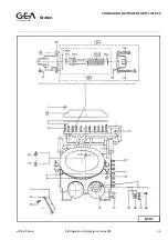
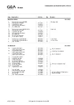
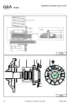
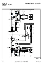
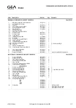
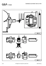
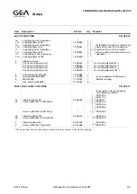
MANUALLY OPERATED CAPACITY CONTROL
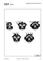
FIG. RC9-12
1
1.1
1.2
1.3
1.4
1.5
1.6
1.7
1.8
1.9
1.10
1.11
1.12
1.13
1.14
1.15
1.16A
1.16B
1.17
1.18
Manually capacity control 6x6G13
Oil distributor housing
Plug G13
Alu sealing ring 13.5x20x1
Spring 0.75x5.2x7.5x18
Steel ball W6
Ball bearing 6004
Distributor spindle 42x106
O-ring 2.5x10
O-ring 3.5x44
Cover 90x15
Indication plate 088
Bush 8x8
Socket head screw M10x20
Hand grip 040
Cylinder head screw M4x20
Swivel coupling 6G13
Plug G13
Nipple coupling 6G13
Countersunk head screw M5x10
12.73.114
*
01.36.136
09.12.014
11.31.083
11.19.004
*
*
09.52.252
09.52.350
*
11.76.088
48.46.108
01.04.520
02.49.040
01.68.220
03.39.136
01.36.136
03,38,136
01.69.910
1
1
1
—
1
1
2
1
2
1
1
1
1
3
1
1
—
—
1
4
total quantity: 5
2
3
4
Hex. head bolt M8x16
Lock washer M8
Support I180x240
01.10.416
11.13.401
02.34.824
4
4
1
except 6-cylinder compressors
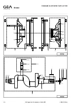
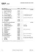
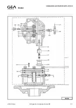
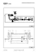
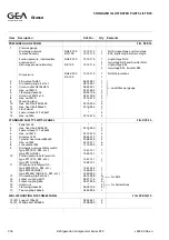
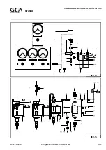
ELECTRICALLY OPERATED CAPACITY CONTROL
FIG. RC9-13
1
2
3
4
5
6
6.1
7
8
9
10
11
12
13
14
15
15.1
16
Support I80x240
Support L30x110A
Hex. head bolt M8x16
Serrated lock washer M8
Hex. nut M8
Three-way solenoid valve 220HB
Valve coil 110-120/50-60
220-240/50-60
Socket coupling 6G10
Angle coupling EV6x6
Tee-coupling EV6x6x6
Nipple coupling 6G10
Socket head screw M5x8
Hex. nut M4
Washer M4
Cylinder head screw M4x16
Junction box (synthetic)
Lamp, bayonet fixing:
24V
48V
110V
220V
Connector
02.34.824
02.38.313
01.10.416
11.13.403
01.15.410
06.80.410
13.16.311
13.16.322
03.37.106
03.52.006
03.54.006
03.38.106
01.04.208
01.15.211
11.13.201
01.68.216
*
13.08.624
13.08.648
13.08.610
13.08.620
13.16.610
13.16.611
13.16.615
1
1
2
2
2
—
—
—
1
(2)
(2)
2
2
2
2
2
1
—
—
—
—
1
1
1
quantities per valve
Without LED
With 220V-AC/DC LED
With 48V-AC/DC LED
Refrigeration Division
Grasso
STANDARD ILLUSTRATED PARTS LIST RC9
v003.99.06.en
Refrigeration Compressors Series RC9
C17

