Component/FRU Removal and Replacement
144
T2100-ST1 Treadmill, 110V / T2100-ST2 Treadmill, 220V
2097937-002 Rev G
11 March 2019
CAUTION:
Use ESD precautions, including wearing a grounding
wrist strap that is connected to an exposed metal
connection point on the treadmill chassis.
6.
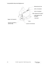
Unplug the 4-conductor JP2 and 3-conductor JP1 plugs
from the SPSR Board (smart power supply relay board).
7.
Unplug the Cooling Fan J1-Red and J2-Black single
conductor spades from the SPSR Board.
8.
Unplug the E-Stop J4-Black and J5-Gray single-conductor
spades from the SPSR Board.
9.
Unplug the Pull Tether J6-Black and J7-Gray single-
conductor spades from the SPSR Board.
10.
Unplug the Speed Sensor J10 two-conductor spade from
the SPSR Board.
11.
Unplug the Elevation Count Sensor J11-three-conductor
spade from the SPSR Board.
12.
Unplug the Drive Harness J15-ten-conductor spade from
the SPSR Board.
13.
Remove the RS232 harness J13 by unscrewing the (2) flat
head screws retaining it to the SPSR Board.
14.
Cut the Zip tie on USB harness J14 and unplug from the
SPSR Board.
15.
Remove the two control board bracket screws.
16.
Remove the screw that holds the circuit board to the
control board bracket.
17.
Relocate the standoff and spacer transfer to the new Power
supply board.
18.
Remove the nylon nuts on the four corners of the SPSR
Board.
19.
Once the board has been removed, note the position of the
voltage switch.
20.
Set the switch on new board to the same voltage as the
board just removed.
NOTICE
Setting a different voltage on the new board will
result in damage!
21.
Reverse the procedure to install the new SPSR Board.
22.
After installation, see Chapter 9, “Calibration”, to
recalibrate the treadmill using the recalibration
instructions for your treadmill model, and then check for
proper operation.

