background image

6-14

F650 Digital Bay Controller

GEK-113000T

6.12 DIRECTIONAL ELEMENTS (67P, 67N, 67G, 67SG)

6 COMMISSIONING

6

6.12DIRECTIONAL ELEMENTS (67P, 67N, 67G, 67SG)

In order to test directional units in the relay, instantaneous trips will be commanded.

Two points will be tested, per phase, test element.

In order to test the directional units, configure (in the "

Setpoint > Relay Configuration > Protection Elements

" screen of

the EnerVista 650 Setup program), some overcurrent element to be supervised by a directional unit. This way, if the
directional element is enabled and detects the fault in the block direction, then the overcurrent unit will not operate. If the
directional element is not enabled or if it is enabled and it detects a fault in a trip direction, then the overcurrent unit will
operate if the set current level is exceeded.

6.12.1 67P ELEMENT

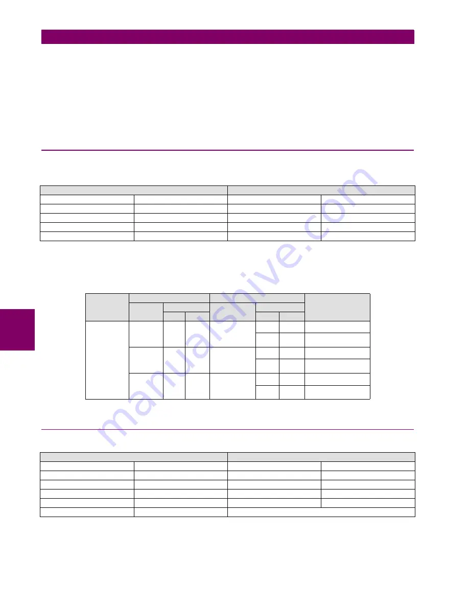
Activate only protection elements 50PH and 67P and set the relay as follows:

Configure one of the outputs to be activated only by unit 50PH.

Apply the following tests:

6.12.2 67N ELEMENT

Activate only protection elements 50N and 67N and set the relay as follows:

Configure one of the outputs to be activated only by unit 50G

.

67P SETTINGS

50PH SETTINGS

Function

ENABLED

Function

ENABLED

MTA

45 Deg

Input

PHASOR (DFT)

Direction

FORWARD

Pickup Level

0.50 A

Block Logic

PERMISSION

Trip Delay

0.30

Pol V Threshold

30 V

Reset Delay

0.00

ELEMENTS

PHASE UNDER TEST

POLARIZATION PHASE

ELEMENT TRIP

CHANNEL MAGNITUDE

CHANNEL

MAGNITUDE

MOD

ARG

MOD

ARG

50PH/67P

IA

2 A

VIII

60 V

NO

60 V

180º

YES

IB

2 A

VI

60 V

NO

60 V

180º

YES

IC

2 A

VII

60 V

NO

60 V

180º

YES

67N SETTINGS

50N SETTINGS

Function

ENABLED

Function

ENABLED

MTA

-45 Deg

Input

PHASOR (DFT)

Direction

FORWARD

Pickup Level

0.50 A

Polarization

VO

Trip Delay

0.30

Block Logic

PERMISSION

Reset Delay

0.00

Pol V Threshold

10 V

Summary of Contents for Multilin GEK-113000T

Page 1: ...om Internet www GEMultilin com Firmware version 3 7X EnerVista F650 Setup version 3 7X Copyright 2007 GE Multilin F650 Digital Bay Controller User manual GEK 113000T GE Multilin Avda Pinoa 10 48170 Zamudio SPAIN T 34 94 485 88 00 F 34 94 485 88 45 E gemultilin euro ge com g GE Consumer Industrial Multilin ...

Page 2: ...G CODE 2 4 TECHNICAL SPECIFICATIONS 2 4 1 PROTECTION ELEMENTS 2 6 2 4 2 CONTROL 2 16 2 4 3 MONITORING 2 20 2 4 4 USER PROGRAMMABLE ELEMENTS 2 22 2 4 5 METERING 2 23 2 4 6 INPUTS 2 24 2 4 7 REAL TIME CLOCK 2 26 2 4 8 OUTPUTS 2 26 2 4 9 CONTROL POWER SUPPLY 2 27 2 4 10 COMMUNICATIONS 2 27 2 4 11 OPTIC FEATURES 2 29 2 4 12 ENVIRONMENTAL CHARACTERISTICS 2 30 2 4 13 PACKAGING AND WEIGHT 2 30 2 4 14 TYP...

Page 3: ...ITY 4 4 LOGING INTO ENERVISTA 650 SETUP 5 BOOTCODE AND FIRMWARE UPGRADE 5 1 INTRODUCTION 5 1 1 COMMUNICATION PARAMETERS 5 2 5 2 BOOT CODE UPGRADE 5 3 FIRMWARE VERSION UPGRADE 5 3 1 FIRMWARE UPGRADE 5 9 5 4 STEP LIST SUMMARY FOR VERSIONS 1 70 AND LATER 5 4 1 BOOT CODE UPGRADE 5 12 5 4 2 FIRMWARE UPGRADE 5 12 6 COMMISSIONING 6 1 VISUAL INSPECTION 6 2 GENERAL CONSIDERATIONS ON THE POWER SUPPLY NETWOR...

Page 4: ... 14 1 59P ELEMENT 6 19 6 14 2 59X ELEMENT 6 19 6 14 3 59NH AND 59NL ELEMENTS 6 20 6 14 4 47 ELEMENT NEG SEQ OV 6 21 6 15 FREQUENCY ELEMENTS 81O 81U 6 16 RECLOSER 79 6 16 1 RECLOSING CYCLE 6 23 6 16 2 RECLOSER STATUS 6 24 6 16 3 EXTERNAL RECLOSE INITIATION 6 24 6 17 THERMAL IMAGE ELEMENT 49 7 FREQUENTLY ASKED QUESTIONS 7 1 COMMUNICATIONS 7 2 PROTECTION 7 3 CONTROL AND HMI 7 4 RELAY CONFIGURATION 8 ...

Page 5: ...4 F650 Digital Bay Controller GEK 113000T TABLE OF CONTENTS ...

Page 6: ...guide you through the initial installation procedures of your new relay BEFORE ATTEMPTING TO INSTALL OR USE THE RELAY IT IS IMPERATIVE THAT ALL WARNINGS AND CAUTIONS IN THIS MANUAL ARE REVIEWED TO HELP PREVENT PERSONAL INJURY EQUIPMENT DAMAGE AND OR DOWNTIME CAUTION THE OPERATOR OF THIS INSTRUMENT IS ADVISED THAT IF THE EQUIPMENT IS USED IN A MANNER NOT SPECIFIED IN THIS MANUAL THE PROTECTION PROV...

Page 7: ...SHALL ONLY BE PERFORMED BY DULY QUALIFIED SERVICE PERSONNEL FOR PERSONAL SECURITY PURPOSES BEFORE ACCOMPLISHING ANY WITHDRAWAL OR INSERTION OPERATION THE RELAY MUST BE POWERED OFF AND ALL THE REAR TERMINALS MUST BE POTENTIAL FREE THE RELAY MUST BE GROUNDED USING THE REAR GROUNDING SCREW Before performing any of these actions control power must be removed from the relay and all the rear terminals m...

Page 8: ...e The current inputs incorporate shorting bars so that the module can be extracted without the need to short circuit the currents externally It is very important for safety reasons not to change or switch the terminals for CTs and VTs Figure 1 3 REAR VIEW OF F650 UNIT GE Multilin will not be responsible for any damage of the relay connected equipment or personnel whenever these safety rules are no...

Page 9: ...elay for physical damage Verify that the model on the label on the side of the relay matches the model ordered Figure 1 4 IDENTIFICATION LABEL A4455P6 Please ensure that you received the following items with your relay Mounting screws for fixing the relay to a cabinet CD containing EnerVista 650 Setup software Wiring diagram Certificate of Compliance ...

Page 10: ...aya SPAIN Tel 34 94 485 88 54 Fax 34 94 485 88 38 E mail multilin tech euro ge com AMERICA ASIA AND AUSTRALIA GE MULTILIN 215 Anderson Avenue L6E 1B3 Markham ON CANADA Tel 1 905 294 6222 Fax 1 905 201 2098 E mail multilin tech ge com The information provided herein is not intended to cover all the details of the variations of the equipment nor does it take into account the circumstances that may b...

Page 11: ...sing a laptop it is recommended not to have it connected to its power supply In many cases it might not be correctly grounded either due to the power supply or to the connector cables used This is required not only for personal protection but also to avoid a potential voltage difference between the relay s serial port and the computer s port which could produce permanent damage to the computer or ...

Page 12: ...cy These objectives are realized through software which is used to perform functions at both the station and supervisory levels The use of these systems is growing rapidly High speed communications are required to meet the data transfer rates required by modern automatic control and monitoring systems In the near future very high speed communications will be required to perform protection signalli...

Page 13: ...al input output contacts from independent modules connected to the 650 unit via a CAN Bus Not available for W650 models PLC Programmable Logic Controller Control module that enables the unit configuration assignment of inputs outputs and the implementation of logic circuits Protection Elements Relay protection elements for example Overcurrent overvoltage etc Not available for C650 models Remote in...

Page 14: ... options are Table 1 1 REAR SERIAL COMMUNICATIONS BOARD 1 The other module provides Ethernet communications COM3 port using 10 100BaseTX self negotiable speed or 100BaseFX connectors depending on the selected model The most complete models include a double redundant 100BaseFX fiber optic port Redundancy is provided at the physical level the unit incorporates internally duplicated and independent c...

Page 15: ...1 10 F650 Digital Bay Controller GEK 113000T 1 2 OVERVIEW 1 GETTING STARTED 1 Figure 1 7 COMMUNICATIONS ARCHITECTURE B6816F1 ...

Page 16: ...Windows 2000 Windows XP Internet Explorer 5 0 or higher 64 MB of RAM 128 MB recommended 40 MB of available space on system drive and 40 MB of available space on installation drive RS232C serial and or Ethernet port for communications to the relay 1 3 2 INSTALLATION After ensuring the minimum requirements for using EnerVista 650 Setup are met see previous section use the following procedure to inst...

Page 17: ...indow as shown below Select the Web option to ensure the most recent software release or select CD if you do not have a web connection then click the Add Now button to list software items for the F650 Figure 1 9 ADD PRODUCT WINDOW 6 If Web option is selected choose the F650 software program and release notes if desired from the list and click the Download Now button to obtain the installation prog...

Page 18: ...in the directory indicated and the installation program will automatically create icons and add EnerVista 650 Setup to the Windows start menu 10 Follow the on screen instructions to install the EnerVista 650 Setup software When the Welcome window appears click on Next to continue with the installation procedure Figure 1 11 ENERVISTA 650 SETUP INSTALLATION 11 When the Choose Destination Location wi...

Page 19: ...plication will be added to is shown in the Selected Program Folder window Click Next to begin the installation process and all the necessary program files will be copied into the chosen directory Figure 1 13 SELECT PROGRAM FOLDER 13 To finish with the installation process select the desired language for startup Figure 1 14 LANGUAGE WINDOW ...

Page 20: ...m the GE EnerVista CD or online from http www GEindustrial com multilin see previous section for installation instructions 2 Go to Communication Computer and enter the following data referring to communications 3 Select Control Type as MODBUS TCP IP from the drop down list This option will display a number of interface parameters that must be entered for proper Ethernet communications 4 Enter the ...

Page 21: ...lowing data referred to communications 3 Select Control Type as No Control Type from the drop down list This option will display a number of interface parameters that must be entered for proper serial communications 4 Enter the relay Slave Address Setpoint Product Setup Communication Settings ModBus Protocol menu in the Slave Address field The default value is 254 5 Enter the physical communicatio...

Page 22: ...to use a shielded twist pair In order to avoid loops where external currents could flow the cable shield must be grounded only at one end The converter box GND terminals are connected to the relay SDA SDB GND terminals respectively For long communications cables longer than 1 km the RS485 circuit must be terminated in an RC network i e 120 ohm 1 nF This circuit is shown on Figure 1 17 RS485 CONNEC...

Page 23: ...r cable is required If the connection is performed through a hub or a switch a direct Ethernet cable is required 1 4 3 FACEPLATE DISPLAY All messages are displayed on a 20x4 character LCD display An optional graphic display is also available Messages are displayed in different languages according to selected model 1 4 4 MAINTENANCE F650 requires a minimum amount of maintenance when it is commissio...

Page 24: ...tting file entries against relay settings schedule 4 Contact inputs and outputs verification This test can be conducted by direct change of state forcing or as part of the system functional testing 5 Visual inspection for any damage corrosion or dust 6 Event recorder file download with further events analysis Unscheduled maintenance such as during a disturbance causing system interruption 1 View t...

Page 25: ...1 20 F650 Digital Bay Controller GEK 113000T 1 4 650 HARDWARE 1 GETTING STARTED 1 ...

Page 26: ...equence of records The internal clock used for time tagging can be synchronized with an IRIG B signal or via the SNTP protocol over the Ethernet port This precise time stamping allows the sequence of events to be determined throughout the system Oscillography data capture may be set to record the measured parameters before and after the event for viewing on a personal computer PC These tools signi...

Page 27: ... and Low 50SG Ground Instantaneous Overcurrent for sensitive ground systems measured from 5th current transformer 50ISG Isolated Ground Instantaneous Overcurrent measured from 5th current transformer 51G Ground Time Overcurrent measured from 4th current transformer 51N Neutral Time Overcurrent calculated from the phase currents 51P Phase Time Overcurrent with Voltage Restraint two elements High an...

Page 28: ...uts 32 Self Reset Virtual Inputs Three Phase Energy IEC 870 5 104 Virtual Outputs up to 512 Frequency ModBus User Map Tripping and closing circuit supervision Sequence components of currents and voltages IEC 61850 Remote Inputs Outputs GSSE and GOOSE messages Pulse Counters Analog Inputs dCmA Analog Comparators USER INTERFACE RECORDS OTHERS Alphanumerical display 4x20 Data Logger Breaking Arcing C...

Page 29: ...N Bus I O REAR ETHERNET COMMUNICATIONS BOARD 2 B 10 100 Base TX C 10 100 Base TX 100 Base FX D 10 100 Base TX Redundant 100 Base FX E Redundant 10 100 Base TX I O BOARD IN SLOT F 1 16 Digital Inputs 8 Outputs 2 8 Digital Inputs 8 Outputs 2 trip close circuit supervision circuits 4 32 Digital Inputs 5 16 Digital Inputs 8 Analog Inputs I O BOARD IN SLOT G 0 None 1 16 Digital Inputs 8 Outputs 4 32 Di...

Page 30: ...w monitoring and configuring these I O boards as if they were internal boards located on slots F and G In this case slots are labeled as H y J The required information to completely define a CIO Module is shown on Table 2 2 Table 2 2 ORDERING CODE FOR CIO MODULE 1 The digit selected for option J must be equal or higher than the digit selected for option H for models including boards 4 and 5 CIOH1J...

Page 31: ... PHASE TIME OVERCURRENT 51PH 51PL Current Input Phasor without harmonics or RMS Rated current For connection to 1 or 5 A CTs Pickup level 0 05 to 160 00 A in steps of 0 01 A Dropout level 97 to 98 of the pickup level Level Accuracy Values at nominal frequency 0 5 of the reading 10 mA from 0 05 to 10 A 1 5 of the reading for higher values Curve Shapes IEEE extremely very moderately inverse IEC A B ...

Page 32: ...me delayed according to IEEE Timing accuracy Operate at 1 03 times the pickup 3 of operate time or 50 ms whichever is greater Saturation Level 48 times the pickup level Snapshot Events Selectable by setting Current Input Fundamental Phasor without harmonics Pickup level 0 05 to 160 00 A in steps of 0 01 A Dropout level 97 to 98 of the pickup level Level Accuracy Values at nominal frequency 0 5 of ...

Page 33: ... Curve Multiplier Time Dial 0 00 to 900 00 s in steps of 0 01 s Reset type Instantaneous or time delayed according to IEEE Timing accuracy Operate at 1 03 times the pickup 3 of operate time or 50 ms whichever is greater Saturation Level 48 times the pickup level Snapshot Events Selectable by setting Current Input Phasor without harmonics or RMS Rated current For connection to 1 or 5 A CTs Pickup l...

Page 34: ...x Pickup at 50 Hz typically Timing accuracy at 0 ms time delay no intentional delay 50ms at non zero time delay 3 of operate time or 50 ms whichever is greater Snapshot Events Selectable by setting Current Input Phasor without harmonics or RMS Rated current For connection to 1 or 5 A CTs Pickup level 0 005 to 16 000 A in steps of 0 001 A Dropout level 97 to 98 of the pickup level Level Accuracy Va...

Page 35: ...n zero time delay 3 of operate time or 50 ms whichever is greater Snapshot Events Selectable by setting Current Input Fundamental Phasor without harmonics Pickup level 0 05 to 160 0 A in steps of 0 01 A Dropout level 97 to 98 of the pickup level Level Accuracy Values at nominal frequency 0 5 of the reading 10 mA from 0 05 to 10 A 1 5 of the reading for higher values Curve Shapes IEEE extremely ver...

Page 36: ...tage VN measured or calculated selected by setting Polarizing Current Isg measured from 5th current transformer Operating Current Ig measured from 4th current transformer Polarizing Voltage threshold 0 to 300 Vac in steps of 1 V Polarizing Current threshold 0 005 A Characteristic angle 90º to 90º in steps of 1º Block Logic Permission or Block selectable by setting Angle accuracy 2º for I 0 1 A and...

Page 37: ...evel 0 05 to 160 0 A in steps of 0 01 A Dropout level 97 to 98 of the pickup level Level Accuracy Values at nominal frequency 0 5 of the reading 10 mA from 0 05 to 10 A 1 5 of the reading for higher values Timing accuracy 3 5 of operate time or 50 ms whichever is greater Heating constant 3 0 to 600 0 minutes in steps of 0 1 minute Cooling constant 1 00 to 6 00 times the heating constant in steps o...

Page 38: ... Logic Any Two All phases logic selectable by setting Supervised by Breaker Selectable by setting Snapshot Events Selectable by setting Voltage Input Fundamental Phasor of the neutral voltage Pickup level 3 to 300 in steps of 1 V Dropout level 97 to 98 of the pickup level Level accuracy 1 reading 0 1 Full Scale from 10 to 275 V at nominal frequency Trip delay 0 00 to 900 00 s in steps of 0 01 s Re...

Page 39: ...age Input Fundamental Phasor of the auxiliary voltage Pickup level 3 to 300 V in steps of 1 V Dropout level 97 to 98 of the pickup level Level accuracy 1 reading 0 1 Full Scale from 10 to 275 V at nominal frequency Curve Shapes Fixed time or inverse curve Reset type Instantaneous Curve Multiplier Time Dial 0 00 to 900 00 s in steps of 0 01 s Timing accuracy 3 5 of operate time or 50 ms whichever i...

Page 40: ...W in steps of 0 01 MW Dropout level 97 to 98 of the pickup level Level accuracy for primary magnitudes 3 complete range Trip delay two stages 0 00 to 900 00 s in steps of 0 01 s Timing accuracy 3 5 of operate time or 50 ms whichever is greater Block Time after close 0 00 to 900 00 s in steps of 0 01 s Snapshot Events Selectable by setting Current Voltage Fundamental Phasor primary values Number of...

Page 41: ...of 0 01 Power Pickup Level 0 01 to 4 50 Watts in steps of 0 01 Characteristic Angle MTA 0 to 360º in steps of 1 Power Pickup Delay 0 00 to 600 00 seconds in steps of 0 01 Level Accuracy for Power 1 of the reading at 0 8 PF 1 and 0 8 PF 1 Curve Shapes Inverse Curve Definite time FlexCurve A B C D user curve Curve Multiplier Time Dial 0 02 to 2 00 s in steps of 0 01 s Tripping time accuracy 3 5 of o...

Page 42: ... Phasor without harmonics Rated current For connection to 1 or 5 A CTs Pickup level for supervision 0 05 to 160 00 A in steps of 0 01 A Pickup level for high level 0 05 to 160 00 A in steps of 0 01 A Pickup level for low level 0 05 to 160 00 A in steps of 0 01 A Pickup level for internal arcing 0 05 to 160 00 A in steps of 0 01 A Dropout level 97 to 98 of the pickup level Level Accuracy 0 5 of the...

Page 43: ... x Pickup at 50 Hz typically Timing accuracy 3 of operate time or 50 ms whichever is greater Snapshot Events Selectable by setting Number of Pulse counters available Up to 8 Multiplier factor 0 000 to 65000 000 in steps of 0 001 Overload factor 0 to 1000000 in steps of 1 Board Origin All available input outputs boards in the device See ordering code F G H J Input origin up to 32 depending on the b...

Page 44: ...quency Rate delay 0 00 to 60 00 s in steps of 0 01 Snapshot Events Selectable by setting Responds to Positive sequence quantities Minimum voltage 0 00 to 300 00 V in steps of 0 01 Reach sec Ω 0 02 to 250 00 Ω in steps of 0 01 Impedance accuracy 3 Angle 5 to 50º in steps of 1 Angle accuracy 3º Pickup delay 0 000 to 65 535 s in steps of 0 001 Reset delay 0 000 to 65 535 s in steps of 0 001 Time accu...

Page 45: ... PLC Data 5 current channels and 4 voltage channels Up to 16 digital channels programmable through PLC Data Storage In non volatile memory flash without battery Format International Standard COMTRADE ASCII IEEE C37 111 1999 Automatic Overwrite Selectable by setting Oscillography records can be concatenated Snapshot Events Selectable by setting Method Single ended Positive Sequence Module 0 01 to 2...

Page 46: ...grammable through PLC Time tag 1 ms using an internal clock of 100 µs Timing Accuracy 1 ms using the IRIG B synchronization input Triggers By any digital signal programmable through PLC Alarm Possibility to display the event as an alarm on the alarms panel Information available always through Communications for all models and also in HMI for models with graphical display M in ordering code Data St...

Page 47: ...gical gates fully programmable by user To create user programmable logic to be distributed as a single object Inputs Any logical variable contact or virtual input Number of timers 8 maximum in each logic scheme provided in library format Number 4 A through D Reset points 40 0 through 1 of pickup Operate points 80 1 through 20 of pickup Time delay 0 to 65535 ms in steps of 1 Saturation Level 20 tim...

Page 48: ...s In graphical displays only Number of selectable displays Logotype metering or both in scrolling mode can be selectable as default screen in text display for all models basic and mimic The metering screen contains current and voltages for phases and ground in primary values Number of configurable Keys 5 Operation drive PLC operands Accuracy 0 5 of the reading 10 mA from 0 05 to 10 A for phases an...

Page 49: ...ase only Update rate 100 ms Accuracy 0 02 Parameters 3 Phase and single phase Accuracy For firmware version 3 00 and former ones 10 mHz at 50 Hz 12 mHz at 60 Hz For firmware version 3 20 and later ones 30 mHz at 50 Hz 36 mHz at 60 Hz Accuracy 3º CT Ratio 1 0 to 6000 0 in steps of 0 1 Rated currents Appropriate for 1 or 5 A F650 has universal range for CT valid for 1 or 5 A to only one terminal Rel...

Page 50: ...e supervision inputs 2 mA V 100 kOhm Voltage threshold for voltage supervision inputs 10 V fixed Debounce Time 1 to 50 in steps of 1 ms Recognition time 1ms Timing resolution 1 ms For Input Activation Voltage Threshold and Debounce Time there is a single setting for all inputs in the same group inputs sharing the same common Input Type and Delay Input Time are not grouped there is a different sett...

Page 51: ...t 250 Vdc Operate Time 8 ms Contact material Silver Alloy Output Logic Type Output Type and Pulse Output Time are selectable by setting for each output Output Logic Type Positive Negative Output Type Normal Pulse Latch Selectable by setting for each output Pulse Output Time 0 to 60000 ms in steps of 1 ms applicable only to signals set as pulse type Separate operate and reset signal can be configur...

Page 52: ... 1200 2400 4800 9600 19200 38400 57600 y 115200 bauds Default Baud Rate 19200 Protocols available ModBus RTU DNP 3 0 Typical distance 1200 m Isolation 2 kV ASYNCHRONOUS REAR PORTS None or two rear ports depending on model COM1 COM2 rear COM2 multiplexed with front port Type depending on model Model F None Model A Redundant RS485 Model X Redundant RS485 fiber CAN for inputs outputs module Model P R...

Page 53: ... Model B 10 100BaseTX self negotiable Model C 10 100BaseTX 100Base FX Model D 10 100BaseTX redundant 100BaseFX Physical media redundancy Model E Redundant 10 100BaseTX self negotiable ports 10 100BaseTX RJ45 connector 100BaseFX ST connectors Wave length 1300 nm Fiber type multimode 62 5 125 µm or 50 125 µm Protocols available ModBus TCP IP DNP over TCP IP and UDP IP IEC 61850 Http ftp tftp allow t...

Page 54: ...e to a logic 0 input This specification applies to either 62 5 125 µm or 50 125 µm fiber cables 3 This specification is intended to indicate the performance of the receiver section of the transceiver when Input Optical Power signal characteristics are present per the following definitions The Input Optical Power dynamic range from the minimum level with a window time width to the maximum level is ...

Page 55: ...CLASS TEST EMC IEC 61000 4 1 IEC 60255 22 1 III Oscillatory waves immunity IEC 61000 4 2 IEC 60255 22 2 IV Electrostatic discharge immunity test IEC 61000 4 3 IEC 60255 22 3 III Radiated electromagnetic field disturbance test IEC 61000 4 4 IEC 60255 22 4 IV Electrical fast transient IEC 61000 4 5 IEC 60255 22 5 IV Surge immunity test IEC 61000 4 6 IEC 60255 22 6 III Conducted electromagnetic field...

Page 56: ...GEK 113000T F650 Digital Bay Controller 2 31 2 PRODUCT DESCRIPTION 2 5 EXTERNAL CONNECTIONS 2 2 5EXTERNAL CONNECTIONS Figure 2 2 F650 WIRING DIAGRAM 189C4216H2 ...

Page 57: ...F24 F7 CC3 51P BLOCK F25 F8 CC4 67P BLOCK F26 F9 COMMON 1 4 COMMON 1 4 F27 F10 COMMON 5 8 COMMON 5 8 F28 F11 CC5 50G BLOCK F29 F12 CC6 51G BLOCK F30 F13 CC7 79 INITIATE I SENS F31 F14 CC8 79 BLOCK F32 F15 COIL 2 F33 F16 52 a I SENS F34 F17 COIL 2 F35 F18 52 b F36 INPUTS OUTPUTS CONFIGURATION FOR BOARDS F1 AND F2 O7 27 59 PICKUP 50 67G PICKUP 51 67G PICKUP O3 O4 O5 O6 O8 O5 O6 79 BLOCK OUTPUTS F2 T...

Page 58: ...50 Setup software interface 3 1 2 ENERVISTA 650 SETUP SOFTWARE OVERVIEW This software package uses ModBus protocol and it is designed to communicate with a single relay at a time GE offers different communication software packages such as GE POWER which can be used to communicate simultaneously with several relays EnerVista 650 Setup software provides an easy way to configure monitor and manage al...

Page 59: ...a visual display of power system and relay operation data captured during specific triggered events 3 1 2 5 FIRMWARE UPGRADES The firmware of a F650 device can be upgraded locally or remotely via the EnerVista 650 Setup software The corresponding instructions are provided by the EnerVista 650 Setup Help file under the topic Upgrading Firmware Modbus addresses assigned to firmware modules features ...

Page 60: ...ES 3 1 ENERVISTA 650 SETUP SOFTWARE INTERFACE 3 3 1 3 MAIN SCREEN The EnerVista 650 Setup software main window supports the following primary display components Title bar Main menu bar Main icon bar Working area Status bar Figure 3 1 ENERVISTA 650 SETUP MAIN SCREEN Working Area Title ...

Page 61: ...e or even in worst cases the relay and or the computer could result damaged by overvoltages For on line working previously ensure that all relay communication parameters such as baudrate slave ModBus address etc match the computer settings Figure 3 2 COMMUNICATION PARAMETERS MENU The Communication computer screen is divided in several subsections Computer settings Main communication parameters for...

Page 62: ... this option selects ModBus TCP IP communication mode for communication through the Ethernet port In this case the top right window will show the typical parameters to be programmed IP address port address and unit identifier in the MODBUS TCP SETUP section MODEM this option displays the parameter to set in case of using a modem for the communication such as Phone number Time out sec init command ...

Page 63: ... configuration Is it necessary to program additional logic Launch the Logic Configuration tool in EnerVista 650 Setup Setpoint Logic Configuration Create new or modify the existing logic File Open Project Compile and save logic file pep and drawing design aut in Logic Configuration tool Exit PLC Graphic Editor and save the 650 file from the main application menu Is the relay completely configured ...

Page 64: ...PLC Editor Contents Relay configuration file containing all protection elements Settings input output and LEDs configuration graphic display configuration etc Equations corresponding to the logic created and compiled in the PLC Editor PLC project file containing the necessary information relative to the relay model logic libraries included in the project lib graphic file name aut etc PLC Project f...

Page 65: ...Launch the Logic Configuration tool in EnerVista 650 Setup Setpoint Logic Configuration Create new or modify the existing logic File Open Project Compile Run Compile and save logic file pep and drawing design aut in Logic Configuration tool File Save Project Send logic to relay Run Send Equations to Relay and Exit PLC Graphic Editor Is the relay completely configured Save all settings configuratio...

Page 66: ...ts How to transfer to relay Connect with the relay Communications Computer Connect with the relay Communications Computer Send settings and configuration from file Launch 650 Logic equations editor Setpoint Logic Configuration Open the created PLC project File Open Project Compile the project Run Compile Now the logic virtual outputs can be sent directly to relay Run Send Equations to Relay Texts ...

Page 67: ... opened Table 3 3 ENERVISTA 650 SETUP MENUS STRUCTURE FILE SETPOINT ACTUAL OPERATIONS COMMUNICATION SECURITY VIEW HELP New Product Setup Front Panel NA Computer Login user Traces Instruction Manual Open System Setup Status NA Modem Change Password ModBus Memory Map GE Multilin on the web Save Protection Elements Metering NA Troubleshooting User Management Languages About EnerVista 650 Setup Save A...

Page 68: ...nd configuration file Save As Save as 650 settings and configuration file Close Close the opened 650 file in EnerVista 650 Setup Config File 650 Converter Tool to convert the 650 files from one version to another Properties File properties for 650 Get info from relay Retrieve the 650 settings and relay configuration compiled equations from the relay Send info to relay Send and write the 650 settin...

Page 69: ...o fully program the unit The enabled menus in the EnerVista 650 Setup program are File Setpoint Actual Communication View and Help The off line mode displays the File Setpoint Actual Communication Security View and Help submenus to program the unit The Actual values submenus are for structure purposes only Values are not refreshed while the relay is not communicating The Save as and Close submenus...

Page 70: ...select the version and model to be converted to It is possible to change the model type FXGX using the conversion tool It must be taken into account that part of the logic can be readjusted to fit the new input and output boards selection Notice also that the external wiring of inputs and outputs board are different for type 1 2 4 and 5 3 1 7 3 PROPERTIES When this option is selected the program w...

Page 71: ...options and settings for the printing device b PRINT PREVIEW Option to preview the whole settings and configuration file 650 in paper format to be printed as shown in Figure 3 8 Figure 3 8 PRINT PREVIEW OF SETTINGS FILE c PRINT In this option the program will print the relay configuration using the PC default active printer on port COMx or LPT This option is active only in off line mode in file ed...

Page 72: ...tion Configuration of Outputs LEDs Operations Protection Elements Oscillography Control Events Switchgear Inputs Virtual Inputs Operations and HMI Whole relay configuration with internal relay signals or user definable ones as logic virtual outputs Logic Configuration Logic configuration graphic editor PLC Editor It is a PLC Project file editor that contains all the internal drawings used to make ...

Page 73: ...port and slave number for procome protocol Only available for procome models 5 SYSTEM SETUP General Settings This screen describes and enables the settings of the power system where the relay will operate Some of these settings will be used only for metering values presentation purposes however some of them apply directly to the sampling and analog digital conversion process rated frequency settin...

Page 74: ...MENU Options enabled only in On line mode are marked as Options enabled only in Off line mode are marked as PROTECTION ELEMENTS Phase Current All overcurrent grouped functions for phase current Neutral Current All overcurrent grouped functions for neutral current Calculated from phases not measured Ground Current All overcurrent grouped functions for ground current Measured from 4th current input ...

Page 75: ... overcurrent 50G Ground Directional Ground directional unit 67G Voltage current and dual polarization SENSITIVE GROUND CURRENT Sensitive Ground TOC Sensitive ground time overcurrent 51SG Sensitive Ground IOC Sensitive ground instantaneous overcurrent 50SG Isolated Ground IOC Isolated ground overcurrent 50IG Sensitive Ground Directional Sensitive ground directional unit 67SG NEGATIVE SEQUENCE CURRE...

Page 76: ...uency Underfrequency unit 81U Grouped element Overfrequency Overfrequency unit 81O Grouped element Synchrocheck Synchronism check unit 25 Not grouped a single unit provided Autoreclose Recloser 79 Not grouped a single unit provided Breaker Failure Breaker failure 50BF Not grouped a single unit provided VT Fuse Failure Fuse Failure VTFF Not grouped a single unit provided Broken Conductor Broken or ...

Page 77: ...act or virtual input Text configuration is only for off line mode NOTE This screen is used for the configuration of digital channels and oscillography trigger The rest of parameters such as function enabling disabling sampling rate number of oscillography files etc must be set on the Setpoint Product Setup Oscillography menu Control Events Up to 128 user programmable events from any logical variab...

Page 78: ...UES 3 1 ENERVISTA 650 SETUP SOFTWARE INTERFACE 3 The following figures show an example of the default factory configuration for F650 The F650 has no default factory configuration but a possible example could be the following Figure 3 9 RELAY CONFIGURATION Figure 3 10 HMI CONFIGURATION ...

Page 79: ...ng the necessary information relative to the relay model logic libraries included in the project lib graphic file name aut etc aut PLC Project file containing all the drawings used by the logic required by 650 relay based on IEC 61131 3 standard Functional block diagram FDB lib User programmable logic objects Library file to be included as an object in a PLC project Logic packages that can be stor...

Page 80: ... and interlocks are fulfilled Breaker Breaker status open closed or undefined The rest of the status signals corresponding to the switchgear XX configured as breaker are in the Status Switchgear Status Switchgear XX menu Protection Status of all the protection units in the device Control Elements Status of all the control units available in the device Protection Summary This screen shows a complet...

Page 81: ...rmal Model Protection status signals for thermal model Reset alarm and operation signals for phases and for unit besides the thermal image values in percentage for all phases and units Voltage Protection status signals pickups and operations for all voltage functions undervoltage overvoltage neutral overvoltage negative sequence overvoltage and auxiliary under and over voltage Power Protection sta...

Page 82: ...2 t counters alarm signal for KI 2 t etc METERING Primary Values Primary values measurements for currents voltages power energy and demand Secondary Values Secondary values measurements for currents voltages and power Phasor Diagram Current voltage and sequence components Frequency Line and Bus frequencies INPUTS OUTPUTS Contact Inputs Status of digital inputs in the Relay for each board according...

Page 83: ...vailable in on line mode showing all the operations previously configured in the relay with their corresponding texts Table 3 23 GENERAL OVERVIEW OF OPERATIONS MENU Options enabled only in On line mode are marked as Options enabled only in Off line mode are marked as RECORDS Event recorder Retrieval and visualization of snapshot event all and new control events and alarm panel By serial or Etherne...

Page 84: ...erform reading or writing in ModBus addresses for verifying communications and access to different positions in the ModBus memory map Only available if the communication has already been established Go to Communication Troubleshooting An example is provided in Figure 3 12 COMMUNICATION Computer Menu to start communication with the relay Modem Menu to set modem communication parameters only availab...

Page 85: ...ion Firmware is related to the relay internal program designed by GE Multilin which performs the protection and control functions and which is run by the relay main microprocessor Upgrade operating system Serial and Ethernet connection Go to Communications Upgrade operating system This option allows the user to update the relay operative system The operative system or OS is the program that suppor...

Page 86: ...ogic equations This file can be retrieved from the relay using the File Get info from relay option in EnerVista 650 Setup through serial or Ethernet communication File Send info to relay option stores this 650 file in the relay pep aut and lib files contain the logic configuration projects necessary to modify the logic virtual outputs in the relay These files can be stored in the relay using the C...

Page 87: ...l English only and can be obtained from EnerVista 650 Setup program Table 3 26 GENERAL OVERVIEW OF VIEW MENU Options enabled only in On line mode are marked as Options enabled only in Off line mode are marked as 3 1 14 HELP MENU OVERVIEW Complete instructions manual and data about EnerVista 650 Setup release Table 3 27 GENERAL OVERVIEW OF HELP MENU SECURITY Login User Log on menu for EnerVista 650...

Page 88: ...ng code option for the text display model basic and M the code for the mimic display graphical The boot code and firmware versions can be seen in the relay text main screen this screen is the default screen in the text menu for all models After the text F650 appears the relay firmware version 3 44in the example and between brackets the boot program version 4 10 in the example followed by General E...

Page 89: ...e reset The latched conditions can also be reset via communications using the LED reset input to configure this signal go to Setpoint Relay Configuration Protection elements LED RESET INPUT By default this LED reset input signal is set to LEDS RESET operation 3 2 3 PUSHBUTTONS The front panel provides Push buttons keypad 5 user programmable plus ESC non configurable shuttle key or shuttle key for ...

Page 90: ...atus operation inhibited for maintenance and safety can be reach pressing the commands pushbutton during several seconds local remote off sequence The local remote off sequence can be also available through communications see chapter 5 8 with a configurable signal that can be set in the Setpoint Relay Configuration Protection Elements screen 3 2 4 FRONT PORT AND COVER SEALING SYSTEM Figure 3 16 sh...

Page 91: ...menu without changing to other low levels rotate the shuttle key left to move up and right to move down When rotating the shuttle key the selected menu is marked by a single scroll bar character The mark in the right part of any menu means that contains more than one level Figure 3 17 Shows an example of main menu navigation Figure 3 17 NAVIGATION IN MAIN TEXT MENU Symbol Action Performed Navigati...

Page 92: ...on and control settings available in device Press shuttle key to enter next level Move L R to select submenu Press ESC to return to previous level Change Settings Menu that allows changing all protection and control settings available in device Inputs and outputs settings relay configuration and logic configuration are not available in HMI only via EnerVista 650 Setup software Press shuttle key to...

Page 93: ...anel LEDs Status Operation Bits Breaker Protection Protection Blocks Phase Current Neutral Current Ground Current Sens Ground Current Neg Seq Current Thermal Model Voltage Power Control Elements Frequency Synchrocheck Autoreclose Breaker Failure enhanced models only VT Fuse Failure Broken Conductor Setting Groups Locked Rotor Pulse Counters Analog Comparators Load Encroachment Switchgear Status Sw...

Page 94: ...rst Line Header of last level in actual values Phase Current in the example Second Line Data identifier in the example PH IOC1 HIGH A is the pickup signal for the first instantaneous overcurrent function level high for phase A Third line Status of the displayed actual value Fourth Line Relative position in the menu it is the first value of 114 Metering Primary Values Current Voltage Power Energy D...

Page 95: ...UMAN INTERFACES SETTINGS ACTUAL VALUES 3 Figure 3 18 ACTUAL VALUES SCREEN DATA In the Actual Values menus are different types of data each type of data will display its particular status type on and off 0 or 1 ok or fail analog values etc Phase Current PH IOC1 HIGH A PKP OFF 1 114 ...

Page 96: ...ey to enter the metering screen Press esc to exit the metering screen and return to snapshot events menu Figure 3 19 shows an example of snapshot events navigation Press shuttle key from the default main screen and enter in the main text menu Move the shuttle key until a single scroll bar character appears in the left part of Snapshot event header Press shuttle key to enter in the snapshot events ...

Page 97: ...ress the shuttle key for this screen to disappear The HMI will not allow to perform any other operation until the screen is acknowledged In the event of several consecutive faults the HMI will always show the most recent fault and the user will need to acknowledge all of them up to a maximum of ten faults In the second option viewing the fault reports in the menu available in the HMI the Fault Rep...

Page 98: ...tance and date and time Second screen with metering data for that fault record All this data is a summary from the fault report file that can be retrieved via EnerVista 650 Setup software Figure 3 20 FAULT REPORT NAVIGATION IN HMI Possible fault types are as follows GROUND Ground faults AG phase A to ground ABG phase AB to ground BG phase BG to ground BCG phase BCG to ground CG phase CG to ground ...

Page 99: ...nd down to visualize the settings selected Table 3 30 GENERAL OVERVIEW OF VIEW CHANGE SETTINGS MAIN MENU MAIN SETTINGS MENU FIRST LEVEL SECOND LEVEL THIRD LEVEL Product Setup Communication Serial Ports Ethernet Ethernet 1 Ethernet 2 ModBus Protocol DNP3 Slave Available for standard and IEC61850 models DNP3 Slave 1 DNP3 Slave 2 DNP3 Slave 3 IEC 870 5 104 Available for standard and IEC61850 models S...

Page 100: ...al Dir 1 Neutral Dir 2 Neutral Dir 3 Ground Current Ground TOC Ground TOC 1 Ground TOC 2 Ground TOC 3 Ground IOC Ground IOC 1 Ground IOC 2 Ground IOC 3 Ground Dir Ground Dir 1 Ground Dir 2 Ground Dir 3 Sens Ground Curr Sens Ground TOC Sens Ground TOC 1 Sens Ground TOC 2 Sens Ground TOC 3 Sens Ground IOC Sens Ground IOC 1 Sens Ground IOC 2 Sens Ground IOC 3 Isolated Gnd IOC Isolated Gnd IOC 1 Isola...

Page 101: ...eutral OV Low 2 Neutral OV Low 3 Neg Seq OV Neg Seq OV 1 Neg Seq OV 2 Neg Seq OV 3 Auxiliary OV Auxiliary OV 1 Auxiliary OV 2 Auxiliary OV 3 Auxiliary UV Auxiliary UV 1 Auxiliary UV 2 Auxiliary UV 3 Power Forward Power Forward Power 1 Forward Power 2 Forward Power 3 Directional Power Directional Power 1 Directional Power 2 Directional Power 3 Watt Gnd Flt High Watt Gnd Flt High 1 Watt Gnd Flt High...

Page 102: ...Overfrequency 2 Overfrequency 3 Synchrocheck Autoreclose Breaker Failure VT Fuse Failure Broken Conductor Broken Conductor 1 Broken Conductor 2 Broken Conductor 3 Locked Rotor Locked Rotor 1 Locked Rotor 2 Locked Rotor 3 Fq Rate of Change Fq Rate of Change 1 Fq Rate of Change 2 Fq Rate of Change 3 Load Encroachment Load Encroachment 1 Load Encroachment 2 Load Encroachment 3 MAIN SETTINGS MENU FIRS...

Page 103: ... Choose the new value moving up and down the shuttle key After selecting the appropriate value press again the shuttle key to fix that value To save the new settings go to the end of the menu rotating the shuttle key right and select the menu Press Enter to save settings When pressing the shuttle key inside this menu the new settings will be saved Select the menu Change settings and press the shut...

Page 104: ...he shuttle key after selecting the desired value press again the shuttle key to store the value Year Date Day Month Year Time Hour Minutes Seconds After storing the value for Year Month will appear between brackets and can be modified Month Date Day Month Year Time Hour Minutes Seconds After storing the value for Month Day will appear between brackets and can be modified Day Date Day Month Year Ti...

Page 105: ...t will be displayed Example of commands operations executions via HMI Press the shuttle key in the menu commands when it is selected in the display All the previously configured commands will be displayed Rotate the shuttle key move through the available commands Press ESC to return to previous level Press shuttle key to pre select the operation to be executed When the message Push Enter for Confi...

Page 106: ...s menu there are three types of functionality Login For entering the password either for settings or commands and enable access to settings or commands Once entering the password the relay is no longer password protected and access is enabled to settings modification or commands execution Logout Once the necessary setting changes or operation commands have been executed the user can log out so tha...

Page 107: ...ser must logout Logout Pwd Settings or Logout Pwd Commands For safety reasons if the user does not log out the relay will do it automatically 15 minutes after the last keypad action d CHANGING THE PASSWORD CHANGE PWD COMMANDS To set a password in the relay both for settings and commands the corresponding menu must be accessed inside the Password menu Change Pwd Settings or Change Pwd Commands To m...

Page 108: ...n the relay logotype including the firmware and boot code versions the relay model and the communication parameters for local port COM2 Figure 3 24 DEFAULT LOGOTYPE SCREEN Metering This option shows a Metering screen including the phase and ground currents as well as phase to phase voltage and zero sequence voltage values all of them in primary values Figure 3 25 DEFAULT METERING SCREEN All This o...

Page 109: ...F2G1HIRF can be displayed in French or in English only by changing the language setting in HMI It is necessary to switch off and on the relay to start working with the new language configuration in the relay In EnerVista 650 Setup it is possible to select the language for the software View Languages Example of language selection in HMI Press the shuttle key to enter the select language menu Depend...

Page 110: ...lity is described in section 3 2 5 in this manual Intro Next Pressing the shuttle key the user access the next graphical screen which in this case corresponds to the primary metering values screen L R Select Once the different switchgear elements to be operated have been configured using EnerVista 650 Setup the user will be able to operate them from the graphic display If a single line diagram has...

Page 111: ...e Frequency Primary Phasor Ib Primary V1 Primary Phase B Reactive Pwr Bus Frequency Primary Phasor Ic Primary V2 Primary Phase B Apparent Pwr Vx Primary Phasor Ig Primary Vab Primary Phase B Real Pwr Pos MVarhour Freeze Phasor Isg Primary Vbc Primary Phase C Reactive Pwr NegMVarhour Freeze Phasor In Primary Vca Primary Phase C Apparent Pwr PosMWatthour Freeze RMS Ia Primary Vn Primary Phase C Real...

Page 112: ... following options at the bottom of the screen next prev reload details At To access the different options in the snapshot events graphic menu the user must move the cursor from left to right The selected option will be displayed in upper case and between brackets To access the selected option the user must press again the shuttle key NEXT The user accesses the next available graphic screen Events...

Page 113: ...ust press the shuttle key A new metering screen will be displayed containing the primary metering values in the snapshot event such as Once inside the Metering screen a new legend will be shown for each event Intro or ESC Prev L R Scroll this legend indicates that by pressing ESC or the shuttle key the system will return to the Event Detail screen and rotating the shuttle key the user will access ...

Page 114: ...ollows Esc Out At Intro Tag event Esc Out At The relative event marking is eliminated and the system returns to the general events screen Intro Tag event If the user places the cursor on a different event by rotating the shuttle key left or right pressing the shuttle key will change the relative mark to that new event 3 2 6 4 NEW EVENTS SCREEN This screen shows the new events that have been produc...

Page 115: ...ion text and its status active ON or inactive OFF In the previous example the produced alarm is the change to local of the execution of operations OPERATIONS IN LOCAL MODE the date and time when this event has been produced and its status ON The bottom of the screen shows the legend that indicates how to navigate through the different options available in the screen ESC Prev Intro Next ESC Prev Pr...

Page 116: ...ify wiring The format of this screen is shown on the figure below The first line shows the name of the screen I O Cards followed by the type and description of the board where the cursor is located which will appear between selection marks and blinking Figure 3 32 INPUTS OUTPUTS GENERAL SCREEN The navigation legend on this screen is as follows Esc Prev Intro Menu L R Chg Card Esc Prev This option ...

Page 117: ...O menu next view test input test output L R Chg Card Moving the shuttle key to the left or right provides access to the status of inputs outputs for the different boards available in the relay TEST INPUT This option allows testing the input activation in emulation mode The displayed screen is similar to the viewing screen but in this case the user can operate the different relay inputs This screen...

Page 118: ...hows the Output name lit up showing that this is an output emulation mode The first relay output will appear blinking and between brackets the user can select a different output by rotating the shuttle key When the shuttle key is pressed the selected output will be activated Navigation through this screen is indicated by the following legend Esc Exit Text Intro Chg Output Esc Exit Text The ESC opt...

Page 119: ...logger and metering values provided by the relay through the web In order to access the different functions provided by the web server the user must simply click on the list name on the left side of the screen The web server for version 1 70 and higher ones allows the user to visualize the different web server screen languages English French Spanish and Russian by pressing the language button on t...

Page 120: ... information provided in this screen includes first the relative event index the lowest index corresponding to the most recent event next the event text that shows the reason for the event its status active ON or inactive OFF and finally the date and time when the event was produced The bottom of the screen shows a Metering screen clicking on one of the events the associated metering values will b...

Page 121: ...red in the Control Events screen inside the Relay Configuration menu of EnerVista 650 Setup Figure 3 36 CONTROL EVENTS SCREEN Unlike the case of Snapshot events in this screen the highest index corresponds to the most recent event The information provided is the control event index the text that has been associated to such event when configured its status active ON or inactive OFF and its date and...

Page 122: ...TTINGS ACTUAL VALUES 3 3 WEB SERVER 3 3 3 4 ALARMS The alarms screen provides access to alarms configured in the relay As in the case of snapshot events and control events this screen allows only to view the alarms but not to acknowledge them Figure 3 37 ALARMS SCREEN ...

Page 123: ... 38 OSCILLOGRAPHY SCREEN If the user clicks on the oscillo record he wants to retrieve the window on the right will show a description of the record header indicating its date time and the most relevant parameters of the record Once a record is selected it is required to press the Download button The system will then open a window to allow saving the files in Comtrade format in the PC hard drive O...

Page 124: ...ety warning message Figure 3 40 FAULT REPORT SCREEN The information provided in this screen includes the date and time when the fault was registered fault calculations such as distance to the fault type of fault date and time and the line parameters as well as the recloser and breaker status during the fault This screen shows also prefault and fault voltage and current primary values At the top of...

Page 125: ... 3 3 3 7 DATA LOGGER The data logger screen allows viewing the data logger first and last value retrieval date and allows downloading the data record files in Comtrade format by pressing the Download option Stored files can be viewed later using any Comtrade format viewer Figure 3 41 DATA LOGGER SCREEN ...

Page 126: ...650 Digital Bay Controller 3 69 3 HUMAN INTERFACES SETTINGS ACTUAL VALUES 3 3 WEB SERVER 3 3 3 8 METERING This screen includes the 53 primary metering values provided by the relay display Figure 3 42 METERING SCREEN ...

Page 127: ...3 70 F650 Digital Bay Controller GEK 113000T 3 3 WEB SERVER 3 HUMAN INTERFACES SETTINGS ACTUAL VALUES 3 ...

Page 128: ...nfirm the delete and if the Administrator chooses yes then the user whose Delete Entry box was checked will be permanently deleted from the list Admin WARNING When this box is checked the user will become an EnerVista 650 Setup Administrator therefore receiving all of the Administrative rights Actual Values When this box is checked the user will have the ability to view Actual Values and all recor...

Page 129: ...nge Password Figure 4 1 CHANGE SECURITY When the operator enters a new password for the first time he she should also enter a personal question that only they could answer There is a limit of 50 characters available to enter the personal question One example as in the above diagram would be What is my mother s maiden name This question will be posed to the user if the user forgets their password a...

Page 130: ...d are granted access as Administrator Security Control can be enabled through Security from the tool bar when logged on as an Administrator Click on User Management and a dialog box will show up Figure 4 2 SECURITY ENABLING Security Control is enabled by checking the ENABLE SECURITY check box The first time the enable security option is selected is necessary to close and open EnerVista 650 Setup t...

Page 131: ...ser For the first log in session of any user name the default password will be password User will be prompt to change the password to something else after the first successfully log in Log on can also be done by clicking Security from the toolbar and choose Login New User User will be prompted with the same log in dialog box for a different user name and password combination In case a user has for...

Page 132: ...l and the default front RS232 port communication parameters Figure 5 1 MAIN SCREEN BOOT CODE RELEASE NOTES It is mandatory to maintain version compatibility between firmware and boot code in the upgrade procedure otherwise the relay will not start after upgrading WARNING BEFORE PERFORMING THE UPGRADE PROCEDURE CHECK THAT BOOT AND FIRMWARE VERSION MATCH FIRMWARE AND BOOT VERSIONS COMPATIBILITY FIRM...

Page 133: ...y to read chapter 5 before accomplishing the F650 UPGRADE PROCEDURE Be aware that boot program and firmware upgrades will erase all the data contained in the relay thus it is advisable to save all the data oscillography events settings and configuration files previously Backward compatibility of PLC projects settings and configuration files is not assured for versions older than 1 13 NOTE RELAYS W...

Page 134: ...y 192 168 37 10 The computer settings have to follow the pattern IP address 192 168 37 XXX Netmask 255 255 255 0 and Gateway 192 168 37 10 if desired XXX is a number between 0 and 255 that is not assigned to any other device to avoid collisions If there are not TCP IP settings according to this pattern in the computer it should be added in order to communicate with the relay following these steps ...

Page 135: ...e Figure 5 3 and add a new address in the PC that corresponds to the same LAN pattern that the relay has in the example bellow 192 168 37 54 Figure 5 4 IP ADDRESS FOR COMPUTER Windows allows Multihosting so it permits having as many IP addresses as desired It is necessary to turn off and on the computer to activate the new address that has been assigned to the PC ...

Page 136: ...tc from the relay before the upgrade It is extremely important to save the relay settings and calibration before continuing with the process Figure 5 5 LOST DATA WARNING MESSAGE To upgrade the boot code it is required to connect an RS232 cable to the front of the relay and an Ethernet cable to the rear port COM3 The serial communication parameters will be the ones selected in the Communications Co...

Page 137: ... is going to be used lately in the relay for Ethernet connection Figure 5 7 TEMPORARY IP ADDRESS SELECTION FOR BOOT UPGRADE After entering the temporary IP address a window will open up for selecting the appropriate file from the Multilin web site or Product CD Figure 5 8 BOOT FILE SELECTION Once the appropriate boot program file has been selected the program will proceed to load the selected file...

Page 138: ...the boot upgrade procedure is the one selected in the Communication computer menu Figure 5 11 ERROR MESSAGE FOR COMMUNICATIONS PROBLEMS After switching the relay off and on if the serial communication between EnerVista 650 Setup and the relay is correct the program shows a message to select to upgrade the current version to the new one Figure 5 12 UPGRADE CURRENT VERSION At this moment selecting Y...

Page 139: ... should match the LAN structure in which the relay will be connected The gateway must be the one used in the LAN structure connecting the relay The relay IP address should have the first three octets corresponding with the Gateway and the last octet must be a free IP address reserved to the relay to avoid possible collisions with other devices After assigning the Ethernet parameters the upgrade of...

Page 140: ...ication with the relay through Ethernet connection has been verified1 enter the EnerVista 650 Setup program select Communication and the Upgrade Firmware Version option At this point proceeding with the upgrade will erase all the data stored in the equipment including the calibration settings in firmware version previous to 1 50 Therefore it is necessary to save all settings to a file before follo...

Page 141: ...E AND FIRMWARE UPGRADE 5 Figure 5 17 FIRMWARE SELECTION WINDOW When upgrading models with Enhanced protection and control functionality see ordering code selection the program will request a password in order to continue with the process Figure 5 18 PASSWORD FOR ENHANCED MODEL UPGRADE ...

Page 142: ...tomatically pre selects the appropriate voltage range for the unit based on the serial number Users can select a different range but if the voltage range is not selected correctly there will be an error in the voltage measurements around 20 due to an incorrect assignment of the calibration values Figure 5 19 VOLTAGE RANGE SELECTION During the process the program displays the files that are being u...

Page 143: ...PROPRIATE IP ADDRESS IN THE PC 5 FROM THE ENERVISTA 650 SETUP PROGRAM SELECT Communications Upgrade Firmware Version 6 ENTER THE IP ADDRESS SERIAL NUMBER AND ORDERING CODE OF THE RELAY TO UPGRADE 7 WHEN REQUIRED BY THE PROGRAM SWITCH OFF AND BACK ON THE RELAY 8 LOCATE THE UPGRADE TXT FILE ACCORDING TO THE MODEL OF THE RELAY 9 PRESS UPGRADE FIRMWARE AND INITIATE THE UPGRADE PROCESS 10 TO COMPLETE T...

Page 144: ...uring transportation and that all screws are correctly fixed and all relay terminal boards are in good condition Verify that the information shown on the relay front plate corresponds to the data shown on the display and to the requested relay model Display information Firmware version Kernel version F650 X XX K KK GENERAL ELECTRIC F650XXXXXXXXX 19200N81 MODBUS 254 Model ...

Page 145: ...for the testing contains wide harmonics the voltmeter and relay responses will be different Relays have been calibrated in factory using a Network of 50 or 60 Hz with a minimum harmonic content When the relay is tested a power supply network with no harmonics in its waveform must be used The ammeters and chronometers used for testing the pickup current and relay operation time must be calibrated a...

Page 146: ...nd WARNING No communication circuit shall be tested for isolation Groups to be created will depend on the type of modules included in F650 selectable according to the model The following table shows the different groups depending on the module type SOURCE 1 G1 H10 H18 G2 H13 H14 H15 SOURCE 2 G1 H1 H9 G2 H4 H5 H6 MAGNETIC MODULE G1 A5 A12 G2 B1 B12 I O F1 MIXED G1 Inp 1 F1 9 G2 Inp 2 F10 18 G3 Out ...

Page 147: ...r GEK 113000T 6 4 INDICATORS 6 COMMISSIONING 6 6 4INDICATORS Feed the relay and verify that when commanding a LED reset operation all LED indicators light up and they are turned off when pressing the ESC key for more than 3 seconds ...

Page 148: ... there is no feed If the power supply source incorporates AC feed this test will be performed also for VAC If the relay incorporates a redundant power supply these tests shall be performed on both power supplies Voltage values to be applied will be the ones indicated below according to the relay model NOTE Codes HIR and LOR correspond to a redundant power supply SUPPLY V MIN V MAX HI HIR 110 250 V...

Page 149: ...IONS Verify that available communication ports allow communication with the relay Ports to be checked are as follows Front RS232 Rear 2 x RS485 2 x Fiber Optic Serial 2 x Fiber Optic Ethernet 1 x RJ45 Ethernet A computer with EnerVista 650 Setup software and an appropriate connector must be used ...

Page 150: ...erify that the relay measures the values with an error lower than 1 5 of the test value or 1 mA whichever is greater for sensitive ground SG GENERAL SETTINGS NAME VALUE UNITS RANGE PHASE CT RATIO 1 0 0 1 1 0 6000 0 GROUND CT RATIO 1 0 0 1 1 0 6000 0 STV GROUND CT RATIO 1 0 0 1 1 0 6000 0 PHASE VT RATIO 1 0 0 1 1 0 6000 0 PHASE VT CONNECTION WYE N A WYE DELTA NOMINAL VOLTAGE 100 V 0 1 1 2250 V NOMI...

Page 151: ...sible error 10 mHz Apply 50 Vac at 60 Hz on channel VII Maximum admissible error 12 mHz Frequency measure on channel Vx terminals A11 A12 Apply 50 Vac at 50 Hz on channel Vx Maximum admissible error 10 mHz Apply 50 Vac at 60 Hz on channel Vx Maximum admissible error 12 mHz Results POWER PER PHASE THREE PHASE POWER P V I Cosϕ P Pa Pb Pc Q V I Senϕ Q Qa Qb Qc APPLIED VOLTAGE AND CURRENT VALUES PER P...

Page 152: ...me common For the first 8 inputs the voltage threshold setting is determined by Voltage Threshold A For the next 8 inputs the setting is Voltage Threshold B Inputs or contact converters CC1 CC16 must also be set to POSITIVE Test settings for mixed board type 2 8 digital inputs 4 blocks for supervision and 8 outputs The inputs test is completed by groups of 4 inputs as this type of board has 2 grou...

Page 153: ...52 a terminals F1 F2 and 52 b terminals F3 F4 Coil 1 circuit supervision inputs and verify that they are activated Remove voltage from both inputs and verify that it takes them 500 ms to change state deactivate Coil 2 Apply 19 Vdc to both 52 a terminals F15 F16 and 52 b terminals F17 F18 Coil 2 circuit supervision inputs and verify that they are activated Apply 19 Vdc to both 52 a terminals F15 F1...

Page 154: ...ELEMENTS 6 6 9CONNECTIONS FOR TESTING PROTECTION ELEMENTS Connect current sources to the relay according to the wiring diagram Current and voltage input terminals are as follows PHASE CONNECTIONS Current IA B1 B2 IB B3 B4 IC B5 B6 IG B9 B10 ISG B11 B12 Voltage VI A5 A6 VII A7 A8 VIII A9 A10 VX A11 A12 ...

Page 155: ...s in a time frame of 10 to 55 ms All the relay trip contacts must operate as well as the contact set as 50 Remove current and apply it again suddenly to a value of 4 times the pickup current The relay should trip instantaneously in a time frame of 10 to 45 ms Test one point for each phase and group of the protection element Note Only available for Enhanced models 50 ELEMENTS TEST PARAMETERS Elemen...

Page 156: ...ts set curve PROTECTION ELEMENT SETTINGS 51PH 51PL 51N 51G AND 46 SETTING VALUE UNIT FUNCTION ENABLED INPUT PHASOR DFT PICKUP LEVEL 1 A CURVE MODIFY FOR EACH TEST TD MULTIPLIER MODIFY FOR EACH TEST VOLTAGE RESTRAINT DISABLED ELEMENT PHASE CURVE TYPE DIAL TIMES IPICKUP TRIPPING TIMES SEC EXPECTED ADMISSIBLE 51PH IA IEEE Ext Inv 0 5 0 9 NA 1 5 11 34 11 00 11 60 5 0 648 0 600 0 710 IB IEC Curve A 0 0...

Page 157: ...ceeded 6 12 1 67P ELEMENT Activate only protection elements 50PH and 67P and set the relay as follows Configure one of the outputs to be activated only by unit 50PH Apply the following tests 6 12 2 67N ELEMENT Activate only protection elements 50N and 67N and set the relay as follows Configure one of the outputs to be activated only by unit 50G 67P SETTINGS 50PH SETTINGS Function ENABLED Function ...

Page 158: ...2 DIRECTIONAL ELEMENTS 67P 67N 67G 67SG 6 Apply the following tests ELEMENTS PHASE UNDER TEST POLARIZATION PHASE ELEMENT TRIP CHANNEL MAGNITUDE CHANNEL MAGNITUDE MOD ARG MOD ARG 50N 67N IA 2 A 0º VI 60 V 0º NO 60 V 180º YES IB 0 A 0º VII 0 V 0º IC 0 A 0º VIII 0 V 0º ...

Page 159: ...tivated only by unit 50G Apply the following tests 67G SETTINGS 50G SETTINGS Function ENABLED Function ENABLED MTA 45 Deg Input PHASOR DFT Direction FORWARD Pickup Level 0 50 A Polarization VO Trip Delay 0 30 Block Logic PERMISSION Reset Delay 0 00 Pol V Threshold 10 V ELEMENTS PHASE UNDER TEST POLARIZATION PHASE ELEMENT TRIP CHANNE L MAGNITUDE CHANNEL MAGNITUDE MOD ARG MOD ARG 50G 67G IG 2 A 0º V...

Page 160: ...d only by unit 50SG Apply the following tests 67SG SETTINGS 50SG SETTINGS Function ENABLED Function ENABLED MTA 45 Deg Input PHASOR DFT Direction FORWARD Pickup Level 0 50 A Polarization VO Trip Delay 0 30 Block Logic PERMISSION Reset Delay 0 00 Pol V Threshold 10 V ELEMENTS PHASE UNDER TEST POLARIZATION PHASE ELEMENT TRIP CHANNEL MAGNITUDE CHANNEL MAGNITUDE MOD ARG MOD ARG 50SG 67SG ISG 2 A 0º VI...

Page 161: ...otection element being tested Set the relay as follows Apply voltage as indicated on the table over the undervoltage setting level and verify that the relay does not trip Decrease voltage level gradually and verify that the relay trips for the set voltage with an admissible error of 5 PHASE UV 27P Function ENABLED Mode PHASE GROUND Pickup Level 50 V Curve DEFINITE TIME Delay 2 00 sec Minimum Volta...

Page 162: ... relay as follows Apply voltage as indicated on the table under the overvoltage setting level and verify that the relay does not trip Verify that the relay trips for the set voltage with an admissible error of 5 PHSE OV 59P Function ENABLED Pickup Level 120 V Trip Delay 2 00 Reset Delay 0 00 Logic ANY PHASE ELEMENT PHASE PICKUP LEVEL VOLTS TRIP DELAY SECONDS APPLIED VOLTAGE V TRIPPING TIME S EXPEC...

Page 163: ...th an admissible error of 5 This element can also be tested by applying only phase voltages For this purpose it is necessary to set Auxiliary Voltage VX In this condition Vn voltage is calculated as a sum of the phase voltages GENERAL SETTINGS Auxiliary Voltage VN NEUTRAL OV HIGH LOW 59NH 59NL Function ENABLED Pickup Level 120 V Trip Delay 2 00 Reset Delay 0 00 ELEMENTS INPUT PICKUP LEVEL VOLTS TR...

Page 164: ...s for the set voltage with an admissible error of 5 NOTE All angles mentioned on the tables are delay angles where a balanced ABC system would be composed by NEG SEQ OV 47 Function ENABLED Pickup Level 50 V Trip Delay 2 00 Reset Delay 0 00 CHANNEL APPLIED VOLTAGE V ANGLE TRIPPING TIME S EXPECTED ADMISSIBLE VI 65 0º NO TRIP NA VII 65 120º VIII 65 240º VI 55 0º 2 1 9 2 1 VII 55 240º VIII 55 120º VI ...

Page 165: ...rips at the set frequency in the corresponding element with an error of 3 ó 50 mHz Apply a voltage that is lower than the Minimum Voltage setting with a frequency under 81U or over 81O the setting and verify that the relay does not trip GENERAL SETTINGS Nominal Frequency 50 Hz ELEMENT SETTINGS FREQUENCY 81 81U 81O Function ENABLED ENABLED Pickup Level 47 50 Hz 52 50 Hz Trip Delay 2 00 sec 2 00 sec...

Page 166: ... recloses in 2 1 seconds Command a 50PH trip and verify that the breaker opens and the relay recloses in 4 1 seconds Command a 50PH trip and verify that the breaker opens and the relay recloses in 6 1 seconds Command a 50PH trip and verify that the breaker opens and the relay recloses in 8 1 seconds Command a 50PH trip and verify that the breaker opens and the recloser passes to Lockout Verify the...

Page 167: ... no reclose INHIBITION BY RECLOSING CONDITIONS Close the breaker and wait for 5 seconds Command a trip verify that the breaker opens and wait for the first shot Activate the inhibition input and command a new trip Verify that the breaker opens wait for 8 seconds and verify that the relay does not reclose 6 16 3 EXTERNAL RECLOSE INITIATION Close the breaker and wait for 5 seconds Activate the reclo...

Page 168: ...ing the thermal element must be reset to zero in order to start the next test at a zero thermal status condition Repeat the test selecting a time constant τ1 of 60 minutes Verify that the operation time is within the range described on the following table After each measuring the thermal element must be reset to zero in order to start the next test at a zero thermal status condition RATED CURRENT ...

Page 169: ...6 26 F650 Digital Bay Controller GEK 113000T 6 17 THERMAL IMAGE ELEMENT 49 6 COMMISSIONING 6 ...

Page 170: ...S232 port whereas the COM1 port is completely independent from COM2 The synchronous LAN port is COM3 Q6 Are there one or two Ethernet ports A6 The equipment has only 1 Ethernet port For redundant fiber optic versions redundancy is done at the physical level fiber optic but there is just one port Q7 How many different communication Ethernet sessions can be opened through the LAN port A7 ModBus TCP ...

Page 171: ...00 it is the 50 125 or 62 5 125 multimode this last one allows longer distances Q16 What is the difference between a hub and a switch A16 In a repeater type hub shared hub one unit talks and the rest listen If all the units are talking at the same time there may be collisions in the messages what may produce certain communication delays The switch switched hub has very powerful processors and a lo...

Page 172: ...e driven with externally generated DC current No special 48 Vdc or other outputs are included in the equipment to drive these inputs therefore contacts connected to the equipment should be connected to a DC source Q3 Is it oscillography programmable A3 Yes the sampling rate is programmable 4 8 16 32 or 64 samples per input The depth will depend on the sampling rate Q4 Do I have to select a differe...

Page 173: ...o program the unit A4 No all main operations can easily be performed with just the incorporated HMI Handheld or laptops may be required to download large quantities of information such as oscillograms etc but they are not mandatory for a conventional user that just needs to change settings view measurements states etc Q5 Is there password security for protection and control A5 Yes there are two pa...

Page 174: ...cess in the logic A1 The power supply ready contact only monitor hardware failures in the power supply to monitor the internal error of the unit it is necessary to configure a virtual output to and the assign it to the device desired contact output LED etc Q2 I set an output contact as Latched If I do not set a reset condition will it reset from the ESC key A2 No you have to configure the contact ...

Page 175: ...7 6 F650 Digital Bay Controller GEK 113000T 7 4 RELAY CONFIGURATION 7 FREQUENTLY ASKED QUESTIONS 7 ...

Page 176: ...g ENERVISTA 650 Setup logic configuration General When feeding the unit no indicator is lit up Insufficient power supply Wrong versions Fuse failure Loose fuse Incorrect wiring Verify the voltage level using a multimeter in the power supply terminals and check that it is within the model range Check relay and ENERVISTA 650 Setup versions are the same Remove power supply dismount the power supply m...

Page 177: ...cation Enervista 650 Setup does not retrieve osc fault reports and Data Logger files Bad communication in TFTP using Windows 2000 Disable and Enable the Ethernet connection on Control Panel inside Windows 2000 Try again to retrieve files from relay Firmware and bootware upgrade Bootware The relay gets stuck during the upgrading process after switching off and on the relay giving the following erro...

Page 178: ...age Os Loading and the relay will not start up Firmware The procedure can not start due to ethernet problems The Ethernet connection does not work properly Check the same as in the point above for bootware Note if the firmware upgrading procedure got stuck at this point the relay will not be upgraded After switching it off and on will continue working with the former firmware and bootware versions...

Page 179: ...d again during the bootware and firmware upgrade process the program will ask to confirm the IEC password Firmware Password for IEC61850 incorrect Model change Incorrect mac or serial number The password is tied to the model MAC Address and serial number any change in any of the following will need a password change If the model has been modified to add or replace any boards or communication proto...

Page 180: ...d BOARD H STATUS Board H status 0 Inactive There is no communication with the board 1 Active There is communication with the board BOARD J STATUS Board J status 0 Inactive There is no communication with the board 1 Active There is communication with the board IEC61850 INTERNAL STATES NON CRITICAL IEC61850 Internal States ICD STATUS UNKNOWN when the relay has not the IEC61850 proto col in the relay...

Page 181: ... Configured FLEXCURVE D STATUS User curve D 0 Not configured 1 Configured Green Zone Memory internal status Yellow Zone Memory internal status Orange Zone Memory internal status Red Zone Memory internal status UpTime System Time Autocheck Internal States Not available TIMER STATUS Real time clock autocheck not available GRAPHIC STATUS Graphic display status not available ALARM TEXT ARRAY Text disp...

Page 182: ...s 24 elements OPERATION BIT 1 Operation bit 001 0 the configured time expires or when success conditions are met 1 operation 1 is executed and interlocks are fulfilled OPERATION BIT 2 Operation bit 002 0 the configured time expires or when success conditions are met 1 operation 2 is executed and interlocks are fulfilled OPERATION BIT 24 Operation bit 024 0 the configured time expires or when succe...

Page 183: ...X CONT IP_X_CC2 Input 2 CC2 in Board X CONT IP_X_CC8 Input 8 CC8 in Board X CONT IP_X_CC9 Va_COIL1 Contact Input 09 Va_COIL1 for slot X Input voltage Va detected Circuit 1 Complete circuit supervised CONT IP_X_CC10 Vb_COIL1 Contact Input 10 Vb_COIL1 for slot X Input voltage Vb detected Circuit 1 Complete circuit supervised CONT IP_X_CC11 Va_COIL2 Contact Input 11 Va_COIL2 for slot X Input voltage ...

Page 184: ...tivation Board X CONT OP OPER_X_08 Logic signal for Output 8 activation Board X Contact Outputs Type 1 2 Board Reset signals CONT RESET_X_01 board X 01 latched output reset CONT RESET_X_02 board X 02 latched output reset CONT RESET_X_08 board X 08 latched output reset Contact Outputs Type 1 2 Board Status CONT OP_X_01 Contact output 1 Board X operation CONT OP_X_02 Contact output 2 Board X operati...

Page 185: ... open SWITCH 2 CLOSED Switchgear 2 closed SWITCH 2 00_ERROR Error 00 switchgear 2 contact A 0 contact B 0 SWITCH 2 11_ERROR Error 11 switchgear 2 contact A 1 contact B 1 SWITCH 16 OPEN Switchgear 16 open SWITCH 16 CLOSED Switchgear 16 closed SWITCH 16 00_ERROR Error 00 switchgear 16 contact A 0 contact B 0 SWITCH 16 11_ERROR Error 11 switchgear 16 contact A 1 contact B 1 Switchgear Open Close Init...

Page 186: ... Reset by hardware ESC and programmable LED RESET INPUT LED 8 Programmable LED 8 status Orange colour Not latched Latching possibility via PLC Reset by hardware ESC and programmable LED RESET INPUT LED 9 Programmable LED 9 status Orange colour Not latched Latching possibility via PLC Reset by hardware ESC and programmable LED RESET INPUT LED 10 Programmable LED 10 status Orange colour Not latched ...

Page 187: ...Selection CHANGE LOCAL REMOTE Changing local remote status by communications CHANGE OP BLOCKED Operations Block Unblock signal HMI Tab Order Selection Swithgear selection status in HMI HMI Tab Order 01 HMI element 1 selection 0 Not selected 1 Selected The selection is performed through the SEL front key When the element 1 has it selection enabled it can be commanded through the O and I front keys ...

Page 188: ...ive OSC DIG CHANNEL 10 Oscillography Digital channel 10 1 Active 0 Not Active OSC DIG CHANNEL 11 Oscillography Digital channel 11 1 Active 0 Not Active OSC DIG CHANNEL 12 Oscillography Digital channel 12 1 Active 0 Not Active OSC DIG CHANNEL 13 Oscillography Digital channel 13 1 Active 0 Not Active OSC DIG CHANNEL 14 Oscillography Digital channel 14 1 Active 0 Not Active OSC DIG CHANNEL 15 Oscillo...

Page 189: ...activation and deactivation of groups 2 3 GROUP 2 ACT ON Group 2 activation and deactivation of groups 1 3 GROUP 3 ACT ON Group 3 activation and deactivation of groups 1 2 Setting Groups SETT GROUPS BLOCK Group change input blocked GROUP 1 BLOCKED Settings Group 1 blocked GROUP 2 BLOCKED Settings Group 2 blocked GROUP 3 BLOCKED Settings Group 3 blocked ...

Page 190: ... HIGH OP Phase instantaneous overcurrent element operation trip high level Group 1 any phase PH IOC2 HIGH A BLK Phase instantaneous overcurrent element block Group 2 phase A PH IOC2 HIGH B BLK Phase instantaneous overcurrent element block Group 2 phase B PH IOC2 HIGH C BLK Phase instantaneous overcurrent element block Group 2 phase C PH IOC2 HIGH A PKP Phase instantaneous overcurrent element picku...

Page 191: ...evel Group 3 phase A PH IOC3 HIGH B PKP Phase instantaneous overcurrent element pickup high level Group 3 phase B PH IOC3 HIGH B OP Phase instantaneous overcurrent element operation trip high level Group 3 phase B PH IOC3 HIGH C PKP Phase instantaneous overcurrent element pickup high level Group 3 phase C PH IOC3 HIGH C OP Phase instantaneous overcurrent element operation trip high level Group 3 p...

Page 192: ...up low level Group 1 any phase PH IOC1 LOW OP Phase instantaneous overcurrent element operation trip low level Group 1 any phase PH IOC2 LOW A BLK Phase instantaneous overcurrent element block Low level Group 2 phase A PH IOC2 LOW B BLK Phase instantaneous overcurrent element block Low level Group 2 phase B PH IOC2 LOW C BLK Phase instantaneous overcurrent element block Low level Group 2 phase C P...

Page 193: ... C PH IOC3 LOW C OP Phase instantaneous overcurrent element operation trip low level Group 3 phase C PH IOC3 LOW PKP Phase instantaneous overcurrent element pickup low level Group 3 any phase PH IOC3 LOW OP Phase instantaneous overcurrent element operation trip low level Group 3 any phase Neutral IOC NEUTRAL IOC1 BLOCK Neutral instantaneous overcurrent element block Group 1 NEUTRAL IOC1 PKP Neutra...

Page 194: ...rcurrent element pickup Group 3 GROUND IOC3 OP Ground instantaneous overcurrent element operation trip Group 3 Sensitive Ground IOC SENS GND IOC1 BLK Sensitive ground instantaneous overcurrent element block Group 1 SENS GND IOC1 PKP Sensitive ground instantaneous overcurrent element pickup Group 1 SENS GND IOC1 OP Sensitive ground instantaneous overcurrent element operation trip Group 1 SENS GND I...

Page 195: ...ous overcurrent element operation trip Group 1 ISOLATED GND2 BLK Isolated ground instantaneous overcurrent element block Group 2 ISOLATED GND2 PKP Isolated ground instantaneous overcurrent element pickup Group 2 ISOLATED GND2 OP Isolated ground instantaneous overcurrent element operation trip Group 2 ISOLATED GND3 BLK Isolated ground instantaneous overcurrent element block Group 3 ISOLATED GND3 PK...

Page 196: ...Phase timed overcurrent element operation trip Group 1 any phase PH TOC2 HIGH A BLK Phase timed overcurrent element block Group 2 phase A PH TOC2 HIGH B BLK Phase timed overcurrent element block Group 2 phase B PH TOC2 HIGH C BLK Phase timed overcurrent element block Group 2 phase C PH TOC2 HIGH A PKP Phase timed overcurrent element pickup Group 2 phase A PH TOC2 HIGH A OP Phase timed overcurrent ...

Page 197: ... Group 1 phase C PH TOC1 LOW A PKP Phase timed overcurrent element pickup low level Group 1 phase A PH TOC1 LOW A OP Phase timed overcurrent element operation trip low level Group 1 phase A PH TOC1 LOW B PKP Phase timed overcurrent element pickup low level Group 1 phase B PH TOC1 LOW B OP Phase timed overcurrent element operation trip low level Group 1 phase B PH TOC1 LOW C PKP Phase timed overcur...

Page 198: ... low level Group 3 phase A PH TOC3 LOW B PKP Phase timed overcurrent element pickup low level Group 3 phase B PH TOC3 LOW B OP Phase timed overcurrent element operation trip low level Group 3 phase B PH TOC3 LOW C PKP Phase timed overcurrent element pickup low level Group 3 phase C PH TOC3 LOW C OP Phase timed overcurrent element operation trip low level Group 3 phase C PH TOC3 LOW PKP Phase timed...

Page 199: ...roup 1 SENS GND TOC2 BLOCK Sensitive ground timed overcurrent element block Group 2 SENS GND TOC2 PKP Sensitive ground timed overcurrent element pickup Group 2 SENS GND TOC2 OP Sensitive ground timed overcurrent element operation trip Group 2 SENS GND TOC3 BLOCK Sensitive ground timed overcurrent element block Group 3 SENS GND TOC3 PKP Sensitive ground timed overcurrent element pickup Group 3 SENS...

Page 200: ...al image phase C Group 2 element reset THERMAL2 ALARM Thermal image element alarm any phase Group 2 THERMAL2 OP Thermal image element operation any phase Group 2 THERMAL2 A ALRM Thermal image element alarm phase A Group 2 THERMAL2 A OP Thermal image element operation phase A Group 2 THERMAL2 B ALRM Thermal image element alarm phase B Group 2 THERMAL2 B OP Thermal image element operation phase B Gr...

Page 201: ...t block Group 2 Phase C PHASE DIR2 C OP Phase directional element operation Group 2 Phase C PHASE DIR3 BLK INP Phase directional block Group 3 PHASE DIR3 BLOCK A Phase directional element block Group 3 Phase A PHASE DIR3 A OP Phase directional element operation Group 3 Phase A PHASE DIR3 BLOCK B Phase directional element block Group 3 Phase B PHASE DIR3 B OP Phase directional element operation Gro...

Page 202: ...p 1 SENS GND DIR2 BLK IP Sensitive ground directional element block input Group 2 SENS GND DIR2 BLOCK Sensitive Ground directional element block Group 2 SENS GND DIR2 OP Sensitive Ground directional element operation Group 2 SENS GND DIR3 BLK IP Sensitive ground directional element block input Group 3 SENS GND DIR3 BLOCK Sensitive Ground directional element block Group 3 SENS GND DIR3 OP Sensitive...

Page 203: ...ent operation BC Group 2 PHASE UV2 CA PKP Undervoltage element pickup CA Group 2 PHASE UV2 CA OP Undervoltage element operation CA Group 2 PHASE UV2 PKP Pickup of any of the above mentioned elements PHASE UV2 OP Operation of any of the above mentioned elements PHASE UV3 BLOCK Phase undervoltage element block Group 3 PHASE UV3 A PKP Undervoltage element pickup AG Group 3 PHASE UV3 A OP Undervoltage...

Page 204: ...lement pickup AB Group 2 PHASE OV2 AB OP Overvoltage element operation AB Group 2 PHASE OV2 BC PKP Overvoltage element pickup BC Group 2 PHASE OV2 BC OP Overvoltage element operation BC Group 2 PHASE OV2 CA PKP Overvoltage element pickup CA Group 2 PHASE OV2 CA OP Overvoltage element operation CA Group 2 PHASE OV2 PKP Pickup of any of the above mentioned elements PHASE OV2 OP Operation of any of t...

Page 205: ...age element pickup low level Group 1 NEUTRAL OV1 LOW OP Neutral overvoltage element operation low level Group 1 NEUTRAL OV2 LOW BLK Neutral overvoltage element block low level Group 2 NEUTRAL OV2 LOW PKP Neutral overvoltage element pickup low level Group 2 NEUTRAL OV2 LOW OP Neutral overvoltage element operation low level Group 2 NEUTRAL OV3 LOW BLK Neutral overvoltage element block low level Grou...

Page 206: ...P Negative sequence overvoltage element pickup Group 1 NEG SEQ OV1 OP Negative sequence overvoltage element operation Group 1 NEG SEQ OV2 BLOCK Negative sequence overvoltage element block Group 2 NEG SEQ OV2 PKP Negative sequence overvoltage element pickup Group 2 NEG SEQ OV2 OP Negative sequence overvoltage element operation Group 2 NEG SEQ OV3 BLOCK Negative sequence overvoltage element block Gr...

Page 207: ...FREQ RATE1 OP Frequency rate of change element operation Group 1 FREQ RATE2 BLOCK Frequency rate of change element block Group 2 FREQ RATE2 PKP Frequency rate of change element pickup Group 2 FREQ RATE2 OP Frequency rate of change element operation Group 2 FREQ RATE3 BLOCK Frequency rate of change element block Group 3 FREQ RATE3 PKP Frequency rate of change element pickup Group 3 FREQ RATE3 OP Fr...

Page 208: ...1 Group 3 FWD PWR3 STG1 OP Forward Power element operation level 1 Group 3 FWD PWR3 STG2 PKP Forward Power element pickup level 2 Group 3 FWD PWR3 STG2 OP Forward Power element operation level 2 Group 3 KI2t PHASE A ALARM K I2t phase A Alarm KI2t PHASE B ALARM K I2t phase B Alarm KI2t PHASE C ALARM K I2t phase C Alarm Breaker Maintenance BKR OPENINGS ALARM Maximum Breaker openings alarm BKR OPEN 1...

Page 209: ... UNBLOCK Recloser element unblock by pulse AR INITIATE Reclose initiate AR CONDS INPUT Reclose permission condition in input to Function 1 there are conditions AR CLOSE BREAKER Closing permission for the recloser AR OUT OF SERVICE Recloser out of service AR READY Recloser READY AR LOCKOUT Recloser in LOCKOUT AR BLOCK Recloser BLOCKed AR RCL IN PROGRESS Recloser Cycle in progress AR LCK BY ANOMALY ...

Page 210: ...onal Power element pickup level 2 Group 2 DIR PWR2 STG2 OP Directional Power element operation level 2 Group 2 DIR PWR2 STG PKP Directional power element pickup Group 2 DIR PWR2 STG OP Directional Power element operation Group 2 DIR PWR3 BLOCK Directional power element block Group 3 DIR PWR3 STG1 PKP Directional Power element pickup level 1 Group 3 DIR PWR3 STG1 OP Directional Power element operat...

Page 211: ...mparators Analog Level 01 Analog comparator element level Group 1 Analog Level 02 Analog comparator element level Group 2 Analog Level 20 Analog comparator element level Group 20 Load Encroachment LOAD ENCR1 BLK Load Encroachment element block Group 1 LOAD ENCR1 PKP Load Encroachment element pickup Group 1 LOAD ENCR1 OP Load Encroachment element operation Group 1 LOAD ENCR2 BLK Load Encroachment e...

Page 212: ... current voltage and power High Level Group 2 32N2 HIGH OC PKP wattmetric Ground Fault Element Overcurrent Pickup High Level Group 2 32N2 HIGH OP wattmetric Ground Fault Element Operation High Level Group 2 32N3 HIGH BLOCK wattmetric Ground Fault Element Block High Level Group 3 32N3 HIGH PKP wattmetric Ground Fault Element Global Pickup current voltage and power High Level Group 3 32N3 HIGH OC PK...

Page 213: ...kup current voltage and power Low Level Group 2 32N2 LOW OC PKP wattmetric Ground Fault Element Overcurrent Pickup Low Level Group 2 32N2 LOW OP wattmetric Ground Fault Element Operation Low Level Group 2 32N3 LOW BLOCK wattmetric Ground Fault Element Block Low Level Group 3 32N3 LOW PKP wattmetric Ground Fault Element Global Pickup current voltage and power Low Level Group 3 32N3 LOW OC PKP wattm...

Page 214: ...utput on Remote Output GOOSE 2 Operation GOOSE Rem GOOSE Dig Out 32 1 output on Remote Output GOOSE 32 Operation GOOSE Remote Inputs Remote Input 1 Flag is set logic 1 Remote Input 2 Flag is set logic 1 Remote Input 32 Flag is set logic 1 Remote Devices Remote Device 1 Flag is set logic 1 Remote Device 2 Flag is set logic 1 Remote Device 16 Flag is set logic 1 GOOSE DIG INPUTS Rem GOOSE Dig Input ...

Page 215: ...A 36 F650 Digital Bay Controller GEK 113000T A 1 LOGIC OPERANDS APPENDIXA A ...

Page 216: ... THERMAL1 ALARM 186 THERMAL2 ALARM 187 THERMAL3 ALARM 188 OR3 189 OR3 inOR1 inOR2 inOR3 200 OR3 outOR1 201 NEUTRAL IOC1 PKP 202 NEUTRAL IOC2 PKP 203 NEUTRAL IOC3 PKP 204 NEUTRAL TOC1 PKP 205 NEUTRAL TOC2 PKP 206 VO_004_50N_PKP 207 VO_005_51N_PKP 208 VO_001_THERMAL_ALARM 214 VO_050_50PL_PKP 215 VO_051_50PH_PKP 216 VO_053_51P_PKP 217 VO_007_PHASE_OVERCURRENT_PKP 218 OR inOR1 inOR2 219 VO_005_51N_PKP...

Page 217: ...PKP 196 SENS GND TOC3 PKP 197 VO_002_50SG_PKP 198 VO_003_51SG_PKP 199 inOR1 inOR2 inOR3 outOR1 inOR1 inOR2 inOR3 outOR1 inOR1 inOR2 inOR3 outOR1 OR3 209 NEG SEQ TOC1 PKP 210 NEG SEQ TOC2 PKP 211 NEG SEQ TOC3 PKP 212 VO_006_I2_TOC_PKP 213 OR 223 VO_049_51G_PKP 224 VO_009_GROUND_OVERCURRENT_PKP 225 VO_048_50G_PKP 226 VO_002_50SG_PKP 227 VO_003_51SG_PKP 228 VO_043_50IG_PKP 229 OR3 230 VO_010_SENSITIV...

Page 218: ...ARY UV1 PKP 245 AUXILIARY UV2 PKP 246 AUXILIARY UV3 PKP 247 AUXILIARY OV1 PKP 248 AUXILIARY OV2 PKP 249 AUXILIARY OV3 PKP 250 NEG SEQ OV1 PKP 251 NEG SEQ OV2 PKP 252 NEG SEQ OV3 PKP 253 OR3 254 OR3 255 OR3 256 OR3 257 VO_012_59NH_PKP 258 VO_013_59NL_PKP 259 VO_014_27X_PKP 260 VO_015_59X_PKP 261 VO_016_V2_OV_PKP 262 VO_017_ALL_VOLTAGE_PKP 263 VO_012_59NH_PKP 264 VO_013_59NL_PKP 265 VO_014_27X_PKP 2...

Page 219: ... FWD PWR2 STG2 PKP 350 inOR1 FWD PWR3 STG1 PKP inOR2 351 inOR3 FWD PWR3 STG2 PKP inOR4 inOR5 352 inOR6 VO_023_FORWARD_POWER_PKP outOR1 353 FORWARD POWER DIRECTIONAL POWER VO_025_DIRECTIONAL_POWER_PKP 370 DIR PWR2 STG PKP 371 DIR PWR3 STG PKP 372 OR3 373 inOR1 inOR2 inOR3 outOR1 DIR PWR1 STG PKP 390 OR3 409 FREQ RATE1 PKP 410 FREQ RATE2 PKP 411 FREQ RATE3 PKP 412 VO_052_81DF DT PKP 413 OR3 414 VO_0...

Page 220: ...KP 396 inOR1 inOR2 inOR3 outOR1 VO_029_LOCKED_ROTOR_PKP 404 LOAD ENCROACHMENT PICKUP OR3 417 LOAD ENCR1 PKP 418 LOAD ENCR2 PKP 419 LOAD ENCR3 PKP 420 VO_031_LOAD_ENCROACHMENT_PKP 421 VO_031_LOAD_ENCROACHMENT_PKP 422 OR7 InOR1 InOR2 InOR3 423 InOR4 InOR5 InOR6 InOR7 inOR1 OutOR1 inOR2 inOR3 outOR1 WATTIMETRIC GROUND FAULT PKP OR3 443 32N1 HIGH PKP 444 32N2 HIGH PKP 445 inOR1 32N3 HIGH PKP inOR2 inO...

Page 221: ...VO_065_51N_TRIP 59 VO_067_51G_TRIP 60 PH TOC1 HIGH OP 117 PH TOC2 HIGH OP 118 PH TOC3 HIGH OP 119 PH IOC1 HIGH OP 120 PH IOC2 HIGH OP 121 PH IOC3 HIGH OP 122 PH IOC1 LOW OP 123 PH IOC2 LOW OP 124 PH IOC3 LOW OP 125 THERMAL1 OP 129 THERMAL2 OP 130 THERMAL3 OP 131 NEUTRAL IOC1 OP 132 NEUTRAL IOC2 OP 133 NEUTRAL IOC3 OP 134 NEUTRAL TOC1 OP 135 NEUTRAL TOC3 OP 136 NEUTRAL TOC2 OP 137 GROUND TOC1 OP 14...

Page 222: ...TOC2 OP 127 NEG SEQ TOC3 OP 128 GROUND IOC1 OP 138 GROUND IOC2 OP 139 GROUND IOC3 OP 140 SENS GND IOC1 OP 144 SENS GND IOC2 OP 145 SENS GND IOC3 OP 146 SENS GND TOC1 OP 147 SENS GND TOC2 OP 148 SENS GND TOC3 OP 149 OR3 174 OR3 180 ISOLATED GND1 OP 181 ISOLATED GND2 OP 182 ISOLATED GND3 OP 183 VO_044_50IG_TRIP 184 VO_044_50IG_TRIP 185 inOR1 inOR2 inOR3 outOR1 inOR1 inOR2 inOR3 outOR1 VO_020_ALL_OVE...

Page 223: ...074_59P_TRIP 78 VO_075_59NH_TRIP 79 VO_076_59NL_TRIP 80 VO_077_59X_TRIP 81 VO_078_27X_TRIP 82 PHASE UV1 OP 150 PHASE UV2 OP 151 PHASE UV3 OP 152 PHASE OV1 OP 153 PHASE OV2 OP 154 PHASE OV3 OP 155 NEUTRAL OV1 HIGH OP 156 NEUTRAL OV2 HIGH OP 157 NEUTRAL OV3 HIGH OP 158 NEUTRAL OV1 LOW OP 159 NEUTRAL OV2 LOW OP 160 NEUTRAL OV3 LOW OP 161 AUXILIARY OV1 OP 162 AUXILIARY OV2 OP 163 AUXILIARY OV3 OP 164 ...

Page 224: ...FWD PWR1 STG1 OP 357 FWD PWR1 STG2 OP 358 FWD PWR2 STG1 OP 359 FWD PWR2 STG2 OP 360 FWD PWR3 STG1 OP 361 FWD PWR3 STG2 OP inOR1 inOR2 362 inOR3 VO_024_FORWARD_POWER_TRIP inOR4 inOR5 363 inOR6 outOR1 DIRECTIONAL POWER DIR PWR1 STG OP 380 DIR PWR2 STG OP 381 DIR PWR3 STG OP 382 OR3 383 VO_027_DIRECTIONAL_POWER_TRIP 384 inOR1 inOR2 inOR3 outOR1 OR3 427 OR3 428 inOR1 FREQ RATE1 OP inOR2 inOR3 429 FREQ...

Page 225: ...P 388 VO_028_POWER_TRIP 389 LOCKED ROTOR OR3 398 LOCKED ROTOR1 OP 399 LOCKED ROTOR2 OP 400 LOCKED ROTOR3 OP 401 VO_030_LOCKED_ROTOR_TRIP 402 VO_030_LOCKED_ROTOR_TRIP 403 inOR1 inOR2 inOR3 outOR1 LOAD ENCROACHMENT TRIP LOAD ENCR1 OP 435 LOAD ENCR2 OP 436 LOAD ENCR3 OP 437 OR3 438 VO_032_LOAD_ENCROACHMENT_TRIP 439 OR7 inOR1 inOR2 inOR3 outOR1 440 InOR1 VO_032_LOAD_ENCROACHMENT_TRIP InOR2 InOR3 441 I...

Page 226: ...Address Oct1 0 N A 0 255 2nd octec of IP address IP Address Oct2 0 N A 0 255 3rd octec of IP address IP Address Oct3 0 N A 0 255 4th octec of IP address IP Address Oct4 0 N A 0 255 1st octec of Netmask Netmask Oct1 0 N A 0 255 2nd octec of Netmask Netmask Oct2 0 N A 0 255 3rd octec of Netmask Netmask Oct3 0 N A 0 255 4th octec of Netmask Netmask Oct4 0 N A 0 255 1st octec of Gateway Gateway IP Oct...

Page 227: ...of IP address of DNP master 3 IP Addr Client3 Oct3 0 N A 0 255 4th Octect of IP address of DNP master 3 IP Addr Client3 Oct4 0 N A 0 255 1st Octect of IP address of DNP master 4 IP Addr Client4 Oct1 0 N A 0 255 2nd Octect of IP address of DNP master 4 IP Addr Client4 Oct2 0 N A 0 255 3nd Octect of IP address of DNP master 4 IP Addr Client4 Oct3 0 N A 0 255 4th Octect of IP address of DNP master 4 ...

Page 228: ...L EVENTS 1 16 N A See DNP note2 Size customization and change of DNP Binary Inputs point list Binary Input Block 2 CTL EVENTS 17 32 N A See DNP note2 Size customization and change of DNP Binary Inputs point list Binary Input Block 3 CTL EVENTS 33 48 N A See DNP note2 Size customization and change of DNP Binary Inputs point list Binary Input Block 4 CTL EVENTS 49 64 N A See DNP note2 Size customiza...

Page 229: ...ynchronization Event 0 N A 0 3600 IEC 870 5 104 NOTES Note 1 Cyclic Meter Period 0 value means no spontaneous metering PRODUCT SETUP COMMUNICATION SETTINGS SNTP SETTING DESCRIPTION NAME DEFAULT VALUE STEP RANGE USER VALUE Function permission Function DISABLED N A DISABLED ENABLED Port used UDP port 123 1 1 65535 IP Address OCT 1 Server IP Oct 1 0 1 1 255 IP Address OCT 2 Server IP Oct 2 0 1 1 255 ...

Page 230: ...ence impedance angle Zero Seq Angle 75 1 Deg 25 90 Line length Line Length 100 0 0 1 0 0 2000 0 Display fault on HMI Show Fault On HMI DISABLED N A DISABLED ENABLED Snapshot Event generation Snapshot Events ENABLED N A DISABLED ENABLED SETPOINT PRODUCT SETUP OSCILLOGRAPHY SETTING DESCRIPTION NAME DEFAULT VALUE STEP RANGE USER VALUE Function Permission Function ENABLED N A DISABLED ENABLED Prefault...

Page 231: ... VT connection Phase VT Connection WYE N A WYE DELTA Rated voltage Nominal Voltage 100 0 0 1 1 0 250 0 Rated Frequency Nominal Frequency 50 Hz Hz 50 60 Phase rotation Phase Rotation ABC N A ABC ACB Frequency reference Frequency Reference VI N A VI VII VIII Auxiliary Voltage Auxiliary Voltage VX N A VX VN Snapshot Event generation Snapshot Events DISABLED N A DISABLED ENABLED SETPOINT SYSTEM SETUP ...

Page 232: ...ear 2 Snapshot Events SWGR 2 DISABLED N A DISABLED ENABLED Snapshot Event generation for switchgear 3 Snapshot Events SWGR 3 DISABLED N A DISABLED ENABLED Snapshot Event generation for switchgear 4 Snapshot Events SWGR 4 DISABLED N A DISABLED ENABLED Snapshot Event generation for switchgear 5 Snapshot Events SWGR 5 DISABLED N A DISABLED ENABLED Snapshot Event generation for switchgear 6 Snapshot E...

Page 233: ...DFT N A PHASOR RMS Pickup level Pickup Level 30 00 0 01 A 0 05 160 00 Trip time Trip Delay 0 00 0 01 s 0 00 900 00 Reset time Reset Delay 0 00 0 01 s 0 00 900 00 Snapshot event generation Snapshot Events ENABLED N A DISABLED ENABLED SETPOINT PROTECTION ELEMENTS PHASE CURRENT PHASE DIRECTIONAL PHASE DIRECTIONAL 1 PHASE DIRECTIONAL 2 PHASE DIRECTIONAL 3 SETTING DESCRIPTION NAME DEFAULT VALUE STEP RA...

Page 234: ...apshot Events ENABLED N A DISABLED ENABLED SETPOINT PROTECTION ELEMENTS NEUTRAL CURRENT NEUTRAL DIRECTIONAL NEUTRAL DIRECTIONAL 1 NEUTRAL DIRECTIONAL 2 NEUTRAL DIRECTIONAL 3 SETTING DESCRIPTION NAME DEFAULT VALUE STEP RANGE USER VALUE Function permission Function DISABLED N A DISABLED ENABLED Maximum Torque Angle MTA 45 1 Deg 90 90 Operation Direction Direction FORWARD N A FORWARD REVERSE Polariza...

Page 235: ...tion DISABLED N A DISABLED ENABLED Maximum Torque Angle MTA 45 1 Deg 90 90 Operation Direction Direction FORWARD N A FORWARD REVERSE Polarization type Polarization VO N A V0 IP V0 IP V0 IP Block logic type Block Logic PERMISSION N A BLOCK PERMISSION Polarization voltage threshold Pol V Threshold 10 1 V 0 300 Snapshot event generation Snapshot Events ENABLED N A DISABLED ENABLED SETPOINT PROTECTION...

Page 236: ...s 0 00 900 00 Deviation time to instantaneous Time to inst 0 00 0 01 s 0 00 900 00 Snapshot event generation Snapshot Events ENABLED N A DISABLED ENABLED SETPOINT PROTECTION ELEMENTS SENSITIVE GROUND CURRENT SENSITIVE GROUND DIRECTIONAL SENSITIVE GROUND DIRECTIONAL 1 SENSITIVE GROUND DIRECTIONAL 2 SENSITIVE GROUND DIRECTIONAL 3 SETTING DESCRIPTION NAME DEFAULT VALUE STEP RANGE USER VALUE Function ...

Page 237: ... V 3 300 Trip time Trip Delay 10 00 0 01 s 0 00 900 00 Reset time Reset Delay 0 00 0 01 s 0 00 900 00 Operation logic Logic ANY PHASE N A ANY PHASE TWO PHASES ALL PHASES Snapshot Event generation Snapshot Events ENABLED N A DISABLED ENABLED SETPOINT PROTECTION ELEMENTS VOLTAGE ELEMENTS NEUTRAL OV HIGH NEUTRAL OV HIGH 1 NEUTRAL OV HIGH 2 NEUTRAL OV HIGH 3 NEUTRAL OV LOW NEUTRAL OV LOW 1 NEUTRAL OV ...

Page 238: ...LUE Function permission Function DISABLED N A DISABLED ENABLED Pickup Level Pickup Level 10 1 V 3 300 Curve shape Curve DEFINITE TIME N A DEFINITE TIME INVERSE TIME Time Dial Delay 10 00 0 01 s 0 00 900 00 Snapshot Event generation Snapshot Events ENABLED N A DISABLED ENABLED SETPOINT PROTECTION ELEMENTS POWER FORWARD POWER FORWARD POWER 1 FORWARD POWER 2 FORWARD POWER 3 SETTING DESCRIPTION NAME D...

Page 239: ...00 00 Trip time for stage 2 Stage 2 Time 60 00 0 01 s 0 00 900 00 Snapshot Event generation Snapshot Events ENABLED N A DISABLED ENABLED SETPOINT CONTROL ELEMENTS SETTING GROUP SETTING DESCRIPTION NAME DEFAULT VALUE STEP RANGE USER VALUE Setting Grouping Permission Function DISABLED N A DISABLED ENABLED Active Group Active Group GROUP 1 N A GROUP 1 GROUP 2 GROUP 3 Snapshot Event generation Snapsho...

Page 240: ...10 00 0 01 V 2 00 300 00 Angle Difference Max Angle Difference 10 0 0 1 Deg 2 0 80 0 Frequency Slip Max Freq Difference 20 10 mHz 10 5000 Breaker Closing time Time 0 50 0 01 s 0 01 600 00 Dead Line Dead Bus Function permission DL DB Function DISABLED N A DISABLED ENABLED Live Line Dead Bus Function permission LL DB Function DISABLED N A DISABLED ENABLED Dead Line Live Bus Function permission DL LB...

Page 241: ...NTS VT FUSE FAILURE SETTING DESCRIPTION NAME DEFAULT VALUE STEP RANGE USER VALUE Function permission Function DISABLED N A DISABLED ENABLED Snapshot event generation Snapshot Events ENABLED N A DISABLED ENABLED SETPOINT CONTROL ELEMENTS BROKEN CONDUCTOR BROKEN CONDUCTOR 1 BROKEN CONDUCTOR 2 BROKEN CONDUCTOR 3 SETTING DESCRIPTION NAME DEFAULT VALUE STEP RANGE USER VALUE Function permission Function...

Page 242: ...is X 1 0 0 1 0 0 50 0 Analog Direction for Activation Inside or Outside the Deadband Analog Direction X OUT N A IN OUT Note X is the analog comparator index up to 20 SETPOINT CONTROL ELEMENTS FREQUENCY RATE OF CHANGE FREQUENCY RATE OF CHANGE 1 FREQUENCY RATE OF CHANGE 2 FREQUENCY RATE OF CHANGE 3 SETTING DESCRIPTION NAME DEFAULT VALUE STEP RANGE USER VALUE Function Permission Function DISABLED N A...

Page 243: ... 2 00 70 00 Source of operating current Current selection IN N A IN IG Pickup Level for Overcurrent OC Pickup Level 0 005 0 001A 0 005 0 400 Pickup Delay for Overcurrent OC Pickup Delay 0 2 0 01 s 0 00 600 00 Pickup Level for operating Power Power Pickup 0 01 0 01 W 0 01 4 50 Max torque angle MTA 0 1 Deg 0 360 Pickup Delay for Operating Power Power Pickup Delay 0 2 0 01 s 0 00 600 00 Curve shape C...

Page 244: ... 230 Debounce time for Group A Debounce Time A_X 15 1 ms 1 50 Debounce time for Group B Debounce Time B_X 15 1 ms 1 50 Debounce time for Group C Debounce Time C_X 15 1 ms 1 50 Debounce time for Group D Debounce Time D_X 15 1 ms 1 50 Input type Input Type_X_CCY CCY POSITIVE N A POSITIVE EDGE NEGATIVE EDGE POSITIVE NEGATIVE Input signal time delay Delay Input Time_X_CCY CCY 0 1 ms 0 60000 Output log...

Page 245: ...wo types of board 01 08 SETPOINT INPUTS OUTPUTS REMOTE COMMS SETTING DESCRIPTION NAME DEFAULT VALUE STEP RANGE USER VALUE Remote comms selection Remote Comms NONE N A NONE GSSE GOOSE SETTING DESCRIPTION FOR GOOSE Remote comms selection Remote Comms GSSE N A NONE GSSE GOOSE Device Identification 650 ID F650 N A Hold time signal send by the transmiting device Hold Time 10000 1 ms 1000 60000 Snapshot...

Page 246: ... OP OPER_F_03 50 67G PKP VO_048_50G_PKP CONT OP OPER_F_04 51 67G PKP VO_049_51G_PKP CONT OP OPER_F_05 50 67P PKP VO_051_50PH_PKP VO_050_50PL_PKP CONT OP OPER_F_06 51 67P PKP VO_053_51P_PKP CONT OP OPER_F_07 RECLOSE OPERATION BIT 1 AR CLOSE BREAKER CONT OP OPER_F_08 TRIP OPERATION BIT 2 VO_083_GENERAL_TRIP CONT OP OPER_G_01 Not Configured CONT OP OPER_G_02 Not Configured CONT OP OPER_G_03 Not Confi...

Page 247: ...CKOUT AR LOCKOUT SETPOINT RELAY CONFIGURATION PROTECTION ELEMENTS PROTECTION ELEMENT SOURCE SIGNAL LOGIC SOURCE LOGIC LED RESET INPUT OPERATION BIT 3 CHANGE LOCAL REMOTE Not Configured CHANGE OP BLOCKED Not Configured HMI BACKLIGHT ON Not Configured HMI BACKLIGHT OFF Not Configured PH IOC1 HIGH A BLK GROUP 1 BLOCKED CONT IP_F_CC2 50P BLOCK CC2 PHASE DIR1 A OP NOT LATCHED VIRT IP 1 PH IOC1 HIGH B B...

Page 248: ... IOC1 LOW C BLK GROUP 1 BLOCKED CONT IP_F_CC2 50P BLOCK CC2 PHASE DIR1 C OP NOT LATCHED VIRT IP 2 PH IOC2 LOW A BLK GROUP 2 BLOCKED CONT IP_F_CC2 50P BLOCK CC2 PHASE DIR2 A OP NOT LATCHED VIRT IP 2 PH IOC2 LOW B BLK GROUP 2 BLOCKED CONT IP_F_CC2 50P BLOCK CC2 PHASE DIR2 B OP NOT LATCHED VIRT IP 2 PH IOC2 LOW C BLK GROUP 2 BLOCKED CONT IP_F_CC2 50P BLOCK CC2 PHASE DIR2 C OP NOT LATCHED VIRT IP 2 PH...

Page 249: ...ENS GND DIR1 OP NOT LATCHED VIRT IP 4 SENS GND IOC2 BLK GROUP 2 BLOCKED SENS GND DIR2 OP NOT LATCHED VIRT IP 4 SENS GND IOC3 BLK GROUP 3 BLOCKED SENS GND DIR3 OP NOT LATCHED VIRT IP 4 PH TOC1 HIGH A BLK GROUP 1 BLOCKED CONT IP_F_CC3 51P BLOCK CC3 PHASE DIR1 A OP NOT LATCHED VIRT IP 5 PH TOC1 HIGH B BLK GROUP 1 BLOCKED CONT IP_F_CC3 51P BLOCK CC3 PHASE DIR1 B OP NOT LATCHED VIRT IP 5 PH TOC1 HIGH C...

Page 250: ...K GROUP 3 BLOCKED NEUTRAL DIR3 OP NOT GROUND TOC1 BLOCK GROUP 1 BLOCKED CONT IP_F_CC6 51G BLOCK CC6 GROUND DIR1 OP NOT LATCHED VIRT IP 7 GROUND TOC2 BLOCK GROUP 2 BLOCKED CONT IP_F_CC6 51G BLOCK CC6 GROUND DIR2 OP NOT LATCHED VIRT IP 7 GROUND TOC3 BLOCK GROUP 3 BLOCKED CONT IP_F_CC6 51G BLOCK CC6 GROUND DIR3 OP NOT LATCHED VIRT IP 7 SENS GND TOC1 BLOCK GROUP 1 BLOCKED SENS GND DIR1 OP NOT LATCHED ...

Page 251: ... VIRT IP 10 NEUTRAL OV1 HIGH BLK GROUP 1 BLOCKED LATCHED VIRT IP 12 NEUTRAL OV2 HIGH BLK GROUP 2 BLOCKED LATCHED VIRT IP 12 NEUTRAL OV3 HIGH BLK GROUP 3 BLOCKED LATCHED VIRT IP 12 NEUTRAL OV1 LOW BLK GROUP 1 BLOCKED NEUTRAL OV2 LOW BLK GROUP 2 BLOCKED NEUTRAL OV3 LOW BLK GROUP 3 BLOCKED AUXILIARY UV1 BLOCK GROUP 1 BLOCKED AUXILIARY UV2 BLOCK GROUP 2 BLOCKED AUXILIARY UV3 BLOCK GROUP 3 BLOCKED PHAS...

Page 252: ... BLK IP GROUP 3 BLOCKED FWD PWR1 BLOCK GROUP 1 BLOCKED FWD PWR2 BLOCK GROUP 2 BLOCKED FWD PWR3 BLOCK GROUP 3 BLOCKED PH TOC1 LOW A BLK GROUP 1 BLOCKED CONT IP_F_CC3 51P BLOCK CC3 PHASE DIR1 A OP NOT LATCHED VIRT IP 6 PH TOC1 LOW B BLK GROUP 1 BLOCKED CONT IP_F_CC3 51P BLOCK CC3 PHASE DIR1 B OP NOT LATCHED VIRT IP 6 PH TOC1 LOW C BLK GROUP 1 BLOCKED CONT IP_F_CC3 51P BLOCK CC3 PHASE DIR1 C OP NOT L...

Page 253: ... BLOCK GROUP 1 BLOCKED LOAD ENCR2 BLOCK GROUP 2 BLOCKED LOAD ENCR3 BLOCK GROUP 3 BLOCKED 32N1 HIGH BLOCK GROUP 1 BLOCKED 32N2 HIGH BLOCK GROUP 2 BLOCKED 32N3 HIGH BLOCK GROUP 3 BLOCKED 32N1 LOW BLOCK GROUP 1 BLOCKED 32N2 LOW BLOCK GROUP 2 BLOCKED 32N3 LOW BLOCK GROUP 3 BLOCKED THERMAL1 A RST OPERATION BIT 4 THERMAL1 B RST OPERATION BIT 4 THERMAL1 C RST OPERATION BIT 4 THERMAL2 A RST OPERATION BIT ...

Page 254: ..._069_GROUND_OVERCURRENT_T RIP DIG_CHANNEL 4 27 TRIP VO_073_27P_TRIP DIG_CHANNEL 5 59 TRIP VO_074_59P_TRIP DIG_CHANNEL 6 PICKUP VO_085_GENERAL_PKP DIG_CHANNEL 7 50 51P PICKUP VO_007_PHASE_OVERCURRENT_PKP DIG_CHANNEL 8 50 51G PICKUP VO_009_GROUND_OVERCURRENT_P KP DIG_CHANNEL 9 27 PICKUP VO_045_27P_PKP DIG_CHANNEL 10 59 PICKUP VO_046_59P_PKP DIG_CHANNEL 11 79 READY AR READY DIG_CHANNEL 12 79 IN PROG ...

Page 255: ...ation5 BRK COUNTERS RESET INTERLOCK LOGIC Not configured FINAL STATES AND LOGIC Not configured FRONT KEY Not configured INPUT Not configured VIRTUAL OUTPUT Not configured TIMEOUT 500 CHANNELS ALL Operation6 ENERGY RESET INTERLOCK LOGIC Not configured FINAL STATES AND LOGIC Not configured FRONT KEY Not configured INPUT Not configured VIRTUAL OUTPUT Not configured TIMEOUT 500 CHANNELS ALL Operation7...

Page 256: ...D LOGIC Not configured FRONT KEY Not configured INPUT Not configured VIRTUAL OUTPUT Not configured TIMEOUT Not configured CHANNELS Not configured SETPOINT RELAY CONFIGURATION EVENTS EVENT NAME SOURCE SIGNAL LOGIC SOURCE LOGIC EV1 Not Configured EV2 Not Configured EV128 Not Configured SETPOINT RELAY CONFIGURATION SWITCHGEAR SWITCHGEAR SETTING VALUE SOURCE SIGNAL LOGIC SOURCE LOGIC SWITCHGEAR 1 CONT...

Page 257: ...TEXT Not Configured ALARM Not Configured OPENING INIT Not Configured CLOSING INIT Not Configured SWITCHGEAR 16 CONTACTS Not Configured OPENING TIME Not Configured CLOSING TIME Not Configured CONTACT A SOURCE Not Configured CONTACT B SOURCE Not Configured OPEN TEXT Not Configured ALARM Not Configured CLOSED TEXT Not Configured ALARM Not Configured ERROR 00 TEXT Not Configured ALARM Not Configured E...

Page 258: ...ective and it is returned with all transportation charges prepaid to an authorized service center or the factory Repairs or replacement under warranty will be made without charge Warranty shall not apply to any relay which has been subject to misuse negligence accident incorrect installation or use not in accordance with instructions nor any unit that has been altered outside a GE Multilin authori...

Page 259: ...D 2 F650 Digital Bay Controller GEK 113000T D 1 GE MULTILIN WARRANTY APPENDIXD D ...

Reviews: