CHAPTER 7: MAINTENANCE
M3 BREAKER MAINTENANCE
350 FEEDER PROTECTION SYSTEM – INSTRUCTION MANUAL
7–7
As long as the current through the Voltage Monitor is above the threshold of the trickle
currents (see Technical Specification for Form A output relays), the circuit integrity for the
Close coil is effectively normal. If the Close coil circuit gets disconnected, or if in general a
high resistance is detected in the circuitry, a Close Coil alarm will be set and the “ALARM”
and “MAINTENANCE” LEDs will be on.
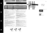
Example 1
: The figure below shows the connection of the breaker close coil to the relay’s
close output relay for voltage monitoring of the close circuit.
NOTE
NOTE:
To monitor the close coil circuit integrity, use the relay terminals “B4” and “A4” to connect
the Close coil, and provide a jumper between terminals “B4” and “B5” (voltage monitor).
Figure 5: Close Coil circuit with voltage monitoring
Example 2
: Some applications require that the Close Coil be monitored continuously,
regardless of the breaker position (open or closed). This can be achieved by connecting a
suitable resistor (see the table) across breaker auxiliary contact 52b in the Close circuit.
With such connections, the trickle current will be maintained by the resistor when the
breaker is closed. For these applications the setting for “BYPASS BKR STATUS” should be set
to ENABLED.
Figure 6: Close Coil circuit with continuous monitoring
The following path is available using the keypad. For instructions on how to use the
keypad, please refer to
Chapter 3 - Working with the Keypad
.
External
jumper
V
B4
A4
B5
Close
Coil
DC +
DC -
Output Relay 2 (CLOSE)
52b
contact
898792.cdr
Close
Coil
DC -
R
By-pass
resistor
52b contact
External
jumper
V
B4
B5
DC +
Close - form A contacts
898793.cdr
A4