


Direction 2233080, Rev 3
High Capacity MOD Option Installation Manual
13
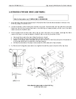
2-4 INSTALLING THE NEW MOD DRIVE (CONTINUED)
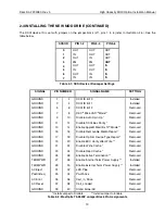
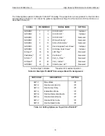
The SCSI device ID is set with jumpers on the jumper block (J7), pins 1 to 6 (refer to Illustration 2-5). See the
table below.
SCSI ID
PIN 1-2
PIN 3-4
PIN 5-6
0
1
2
3
4
5
6
7
OUT
IN
OUT
IN
OUT
IN
OUT
IN
OUT
OUT
IN
IN
OUT
OUT
IN
IN
OUT
OUT
OUT
OUT
IN
IN
IN
IN
Table 2-1: SCSI Device ID Jumper Settings
SIGNAL
PIN NUMBER
SIGNAL NAME
SETTING
GROUND
GROUND
GROUND
GROUND
GROUND
GROUND
GROUND
GROUND
GROUND
GROUND
GROUND
GROUND
GROUND
TERMPWR
TERMPWR
AC Eject
PwrDnReq
AC Error
AC Reset
GROUND
1
3
5
7
9
11
13
15
17
19
21
23
25
27
29
31
33
35
37
39
2
4
6
8
10
12
14
16
18
20
22
24
26
28
30
32
34
36
38
40
SCSI ID Bit 0
SCSI ID Bit 1
SCSI ID Bit 2
DEC
TM
MicroVAX
TM
Mode**
Disable Auto Spin Up *
Disable SCSI Bus Parity *
Enable Apple® Macintosh™ Mode **
Disable Removable Media Report *
Disable Optical Device Type Report *
Enable ECC Verify after Write **
Disable Write Cache *
Disable Read Cache *
Enable Active Termination **
Enable Internal Term Power Supply **
Enable External Term Power Supply **
LED Pipe
PwrDnAck
Cart_in_Drive
Cart_Loaded
Stand Alone/AC
Installed
Installed
Removed
Removed
Removed
Removed
Removed
Removed
Removed
Removed
Removed
Removed
Removed
Installed
Installed
Removed
Removed
Removed
Removed
Removed
*Install Jumper to Disable
**Install Jumper to Enable
Table 2-2: MaxOptix T5-2600P Jumper Block Pin Assignments


