


Direction 2233080, Rev 3
High Capacity MOD Option Installation Manual
9
2-3
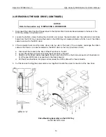
REMOVING THE MOD DRIVE
NOTICE
If working on an MR station where the drive is only an option, refer directly to section 2-4.
If removing a full height WORM drive, care must be given to the wiring of the ribbon cable
and the location of components in the SCSI tray: refer to page 10 for the procedure.
1.
With the SCSI tray removed from the cabinet as described under "Removing the SCSI Tray" in Section 2-2.
2.
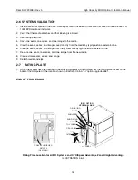
Remove the tape or cartridge drive from the SCSI tray (to access the screws on the MOD drive). Illustration 2-
3 shows the location of each drive.
a.
Disconnect the ribbon cable at the back of the tape or cartridge drive.
b.
Disconnect the power cable at the back of the tape or cartridge drive.
c.
Place the SCSI tray on its side with the tape or cartridge drive at the bottom.
d.
While supporting the tape or cartridge drive, remove the four Phillips screws holding the tape or cartridge
drive to the SCSI tray.
e.
Pull tape or cartridge drive and attached bracket out of the tray.
3.
Remove the MOD drive from the SCSI tray:
a.
Place SCSI tray flat on worktable.
b.
Disconnect the ribbon cable at the back of the MOD drive.
c.
Disconnect the power cable at the back of the MOD drive.
d.
While supporting the MOD drive, remove the four screws holding it.
e.
Pull the MOD drive out of the tray. Leave the mounting bracket in the tray.
MOD
CONTROLLER
MOD
DRIVE
TAPE
DRIVE
or
CARTRIDGE
DRIVE
SEAGATE WREN V
DISK DRIVE
SCSI FAN
Drive Locations on the SCSI Tray
ILLUSTRATION 2-3-A


