


Direction 2233080, Rev 3
High Capacity MOD Option Installation Manual
8
2-2 REMOVING THE SCSI TRAY (CONTINUED)
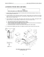
6.
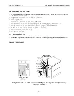
Loosen the two captive screws on the underside of the tray that holds the SCSI tray in place, as shown in
Illustration 2-1-A or 2-1-B.
CAUTION
Once the two screws holding the SCSI tray in place are loosened, the tray is not attached
to the cabinet in any way. Hold on to the tray as you slide it out of the cabinet so that the
tray does not fall to the floor. Lift carefully to avoid injury to yourself.
7.
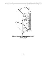
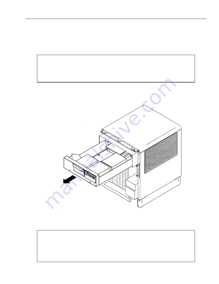
Carefully withdraw the SCSI tray from the front of the cabinet as shown in Illustration 2-2.
8.
Put the SCSI tray flat onto a worktable.
PULL TRAY
STRAIGHT OUT
Removing the SCSI Tray
ILLUSTRATION 2-2
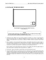
NOTICE
For MR systems that did not have the MOD drive option before, you may need to order
mounting brackets GE P/N 46-306623P1 (right) and 46-306623P2 (left) in order to install the
drive. You also need a dual opening bezel (front panel GE P/N 46-307621P1) if the current
one has only one slotted hole.


