background image

Managing Internal Storage

3.

Use the

trimpad

to select the record you want to edit.

NOTE:

You cannot edit the patient data for records that were imported to internal
storage. Imported records have a

Sent

status of

Recv

.

4.

Press

F1

(

Edit

).

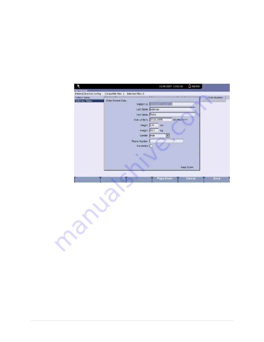
The

Enter Patient Data

window opens.

5.

Edit the information as appropriate.

For instructions on editing patient information, refer to

“Entering Patient

Information” on page 47

.

6.

After the information is updated, press

F6

(

Save

).

The updated information is saved, and you return to the

File Manager

window.

Reviewing Records

Use the following instructions to review recorded patient data:

1.

From the

Main Menu

, press

F3

(

File Manager

).

The

File Manager

window opens.

2.

Press

F5

(

Search

) and use the

trimpad

to select the record(s) you want to review.

3.

Press

F6

(

More

) >

F3

(

Review

).

A window opens with the record for you to review.

4.

After reviewing the record, press

Return

and return to the

File Manager

.

80

MAC™ 800

2060026-001C

Summary of Contents for MAC 800

Page 1: ...Healthcare MAC 800 Resting ECG Analysis System Operator s Manual Software Version 2 0 x 2060026 001 Revision C MAC 800 Resting ECG Analysis System English 2012 General Electric Company All Rights Reserved ...

Page 2: ...equirements concerning medical devices from the following regulatory bodies The document part number and revision appear at the bottom of each page The revision identifies the document s update level The revision history of this document is summarized in the following table Revision Date Comments A 9 February 2012 Internal business release of document B 27 February 2012 Initial customer release of...

Page 3: ...bility of the Manufacturer 17 Responsibility of the Purchaser Customer 17 Symbols 18 Training 21 Equipment Identification 22 Product Label 22 Serial Number Format 22 Product Codes 23 Service Information 23 Service Requirements 23 Hardware Supplied by GE Healthcare 24 Additional Assistance 24 Manual Information 24 Intended Audience 24 Manual Purpose 24 Document Conventions 24 Related Documents 25 2...

Page 4: ...t Preparing the Patient s Skin 41 Electrode Placement 42 Resting ECG Placement 42 4 Entering Patient Information Entering Patient Information Manually 47 Entering Patient Information with a Barcode Reader 48 Entering Patient Information with a Magnetic Card Reader 49 Receive Orders from a MUSE System 50 Preparation 50 Load the Orders 50 Select the Orders to Receive 50 Select an Order to Complete 5...

Page 5: ... Report 71 RR Analysis Options 72 Waveform Options 72 Output Options 73 RR Analysis Setup 74 8 Managing Internal Storage Introduction 77 Importing Records 78 Printing the File Manager Directory 78 Finding Records 79 Editing Patient Data 79 Reviewing Records 80 Deleting Records 81 Printing Records 81 Transmitting Records 81 Exporting Records 82 Setting Up Export Options 83 Exporting Records 83 PDF ...

Page 6: ...ntenance 123 Inspecting the Equipment 124 Cleaning the Device 124 Battery Maintenance 125 Battery Safety 125 Replacing the Battery 126 Conditioning the Battery Pack 126 Supplies and Accessories 127 A Troubleshooting General Troubleshooting Tips 129 Equipment Problems 130 System Does Not Power Up 130 ECG Data Contains Noise 130 ACI TIPI Statement is not Included on Report 131 Paper Jams 131 SD Card...

Page 7: ... Reader 135 Configuring the Barcode Reader Manually 136 Configuring the Barcode Reader Automatically 136 C Magnetic Card Reader Configuration Understanding the Data Header 139 Configuring the Magnetic Card Reader 140 D Product Specifications Specifications 141 2060026 001C MAC 800 7 ...

Page 8: ...8 MAC 800 2060026 001C ...

Page 9: ...ll as used in clinics physician offices outreach centers or wherever ECG testing is performed to record ECG signals from surface electrodes offer two basic modes of operation 1 resting ECG mode and 2 arrhythmia mode print 3 and 6 leads of ECG be upgradeable to provide software options such as 12 lead ECG measurement and interpretive analysis provide for the optional transmission and reception of E...

Page 10: ...int out hazards and to designate a degree or level of seriousness Familiarize yourself with the following definitions and their significance Definitions of Safety Conventions Safety Convention Definition DANGER Indicates an imminent hazard which if not avoided will result in death or serious injury WARNING Indicates a potential hazard or unsafe practice which if not avoided could result in death o...

Page 11: ...charge after defibrillation A residual charge will block acquisition of the ECG signal Whenever patient defibrillation is a possibility use nonpolarizing silver silver chloride construction electrodes for ECG monitoring WARNING MAGNETIC AND ELECTRICAL INTERFERENCE Magnetic and electrical fields are capable of interfering with the proper performance of the device For this reason make sure that all ...

Page 12: ...icable waste control regulations and keeping out of children s reach WARNING ELECTRIC SHOCK To reduce the risk of electric shock do NOT remove cover or back Refer servicing to qualified personnel WARNING BURN PROTECTION To ensure defibrillator protection and protection against high frequency burns use only GE Healthcare recommended cables and leadwires Otherwise serious injury could result WARNING...

Page 13: ...e of applying it properly CAUTION POWER REQUIREMENTS Before connecting the device to the power line check that the voltage and frequency ratings of the power line are the same as those indicated on the device s label If this is not the case do not connect the system to the power line until you adjust the device to match the power source In the U S A if the installation of this equipment will use 2...

Page 14: ...EC and deemed sufficient by GE Healthcare to be in compliance with EN IEC 60601 1 2 when used according to the device or system s intended use Hardware supplied by GE Healthcare meets the applicable country requirements Classification Description Class B The device or system is suitable for use in all establishments including domestic establishments and those directly connected to the public low v...

Page 15: ...user to assess whether they are needed to perform the exam A field RACE is one of these optional fields It has been acknowledged by the medical profession as useful to analyze some pathologies You should be aware that in some jurisdictions the processing of data revealing an individual s racial origin is subject to legal requirements such as obtaining the patient s prior consent If you elect to co...

Page 16: ...esigned to comply with applicable country requirements such as USA FCC 47CFR68 CE EU R TTE 1999 5 EC Refer to the device for a registration number and ringer equivalence number REN The modem is designed for use on standard device telephone lines Connection to telephone company provided coin service central office implemented systems is prohibited Connection to party lines service is subject to sta...

Page 17: ... extending 1 83m 6 ft beyond the normal location of the bed chair table treadmill or other device s supporting the patient during examination and treatment and extending vertically to 2 5m 8 ft 2 4 in above the floor Evidence that the safety certification of the accessory was performed in accordance with the appropriate 60601 1 and or 60601 1 1 standard s Responsibility of the Manufacturer GE Heal...

Page 18: ... equipment The separate collection symbol is affixed to a battery or its packaging to advise you that the battery must be recycled or disposed of in accordance with local or country laws The letters below the separate collection symbol indicate whether certain elements are contained in the battery To minimize potential effects on the environment and human health it is important that all marked bat...

Page 19: ...facturer address Recyclable Atmospheric limits Temperature limits Humidity limits Keep dry Fragile Alternating current Battery symbol The flashing amber LED next to this symbol indicates you must connect the system to AC power to re charge the battery 2060026 001C MAC 800 19 ...

Page 20: ...ina specific Secure Digital SD Card Batch or lot number Authorized European Representative CCC Mark China Compulsory Certification mark TÜV Rheinland NRTL Certification Mark China Metrology Certification Indicates conformity with applicable European directives 20 MAC 800 2060026 001C ...

Page 21: ... Protected against spraying 4 Protected against splashing 5 Protected against jetting 6 Protected against powerful jetting 7 Protected against immersion up to 1 minute 8 Protected against immersion beyond 1 minute USA only For use by or on the order of a Physician or persons licensed by state law Training This manual is intended as a supplement to not a substitute for thorough product training If ...

Page 22: ... the product the label may vary slightly in format but it contains the same information Product Label Format Item Description 1 Product part number 2 Product description 3 Date of manufacture in YYYY MM format 4 Unit serial number See Serial Number Format on page 22 for more information 5 Product barcode Serial Number Format Each device has a serial number that uniquely identifies the device and p...

Page 23: ...ype R the device was refurbished U the device was upgraded to meet the specifications of another product code Product Codes The product code identifies specific system platforms You need the product code before servicing or requesting support for your device You can identify the product code using the device s serial number which can be located in one of the following places On the product label a...

Page 24: ...quest training assistance from GE Healthcare if needed Intended Audience This manual is written for clinical professionals who use maintain and or troubleshoot the system Clinical professionals are expected to have a working knowledge of appropriate medical procedures practices and terminology used in the treatment of patients Manual Purpose This manual describes the safe and effective operation o...

Page 25: ...s to open the Option Activation window Illustrations All illustrations in the manual are provided as examples only Depending on system configuration screens that appear in the manual may differ from the screens as they appear on your system All patient names and data are fictitious Any similarity to actual persons is coincidental Notes Notes provide application tips or additional information that ...

Page 26: ...Introduction 26 MAC 800 2060026 001C ...

Page 27: ...quipment Overview Equipment Description Front View Item Name Description 1 Display Presents waveform and text data 2 Power LED Indicates the device is plugged in and receiving power 2060026 001C MAC 800 27 ...

Page 28: ...tes the system is running 5 Keyboard Input device for controlling the system or entering data See Keyboard Layout on page 30 for more information 6 Writer Prints reports Side View Item Name Description 1 ECG signal input connector D sub 15 pin female connector for the acquisition cable 2 SD card slot Secure Digital card slot Insert card as indicated by the icon The system supports only SD cards fo...

Page 29: ...t of this port indicates network traffic 3 USB connector Universal Serial Bus connector for USB devices such as an optional barcode reader a magnetic card reader an external USB keyboard a laser printer or a USB WiFi device 4 COMM Port Serial connector for data communication with CASE CardioSoft or the MUSE system with a serial cable 5 AC power connector Standard connector for the AC power cable 6...

Page 30: ...d Layout Your keyboard may differ slightly from the following illustration Item Name Description 1 Function Keys F1 through F6 Selects menu options on the screen Refer to Selecting Menu Options on page 39 for details 2 Leads key Changes the leads when the screen is displaying waveforms 3 Power Button Turns the system on and off 30 MAC 800 2060026 001C ...

Page 31: ...cannot be transmitted 7 Stop key Stops the writer from printing 8 Backspace Key Deletes characters 9 Space Key Adds a space between typed characters 10 T9 Key Switches between different input methods For more information refer to Entering Data Using the T9 Key on page 40 Acquisition Modules The system supports a variety of acquisition modules WARNING BURN PROTECTION Using cables other than those s...

Page 32: ...n cable consists of a D sub 15 pin male connector 2 Multi link acquisition cable leads The lead end of the multi link acquisition cable attaches to the leadwire adapters and uses 10 or 12 leadwires 3 NEHB acquisition cable leads The lead end of the NEHB acquisition cable attaches to the leadwire adapters and uses 12 leadwires 4 Value acquisition cable leads The lead end of the value acquisition ca...

Page 33: ...lowing steps 1 Inserting the battery 2 Connecting the AC power adapter 3 Connecting leadwires 4 Inserting paper 5 Connecting a magnetic card reader 6 Connecting a barcode reader 7 Connecting the optional internal modem 8 Connecting the LAN 9 Connecting the external laser printer 10 Turning on the system 11 Configuring the system 12 Testing the equipment Each step is described in more detail on the...

Page 34: ... that is connected to AC power You may begin using the system connected to AC power Do not use the system on battery power until the battery is fully charged as indicated by the on screen battery gauge and the solid amber LED next to the display Connecting the AC Power Adapter The system can run using AC or battery power When the device is plugged into an AC outlet it uses AC power and charges the...

Page 35: ...le end of the device s power cord to the AC power connector on the rear of the device 1 2 Plug the male end of the device s power cord into an AC outlet 2 3 Check the Power LED to make sure the device is receiving power from the AC outlet For more information refer to Front View on page 27 2060026 001C MAC 800 35 ...

Page 36: ...nual for details 2 Connect the leadwires to the front of the acquisition module 1 Refer to Acquisition Modules on page 31 for more information 3 Connect the acquisition cable to the device 2 Ensure the cable is seated snugly Inserting Paper Before printing ECG reports insert the 110 mm z fold paper into the device Refer to the MAC 800 v2 0 Supplies and Accessories Reference Manual for instructions...

Page 37: ... View on page 29 for details Connecting to a LAN If you purchased the LANC LAN Communication to CardioSoft or LANM LAN Communication to MUSE options connect an ethernet cable to the RJ45 network connector on the back of the device See the LAN Option Installation and Troubleshooting Guide for information on configuring the LAN connection If you purchased the WIFC WiFi Communication to CardioSoft or...

Page 38: ...hen the system is ready for operation configure the system settings using the information in System Configuration on page 87 If you are applying the same settings to multiple devices at the site export the settings to an SD card and use that card to import the settings to other devices Testing the Device After the system is set up and configured test it completely before using with patients Test s...

Page 39: ... Options Configure the system and initiate ECG readings by selecting menu options that are arranged across the bottom of the display Up to six menu options are available at any given time and each option corresponds to a function key F1 F6 directly below the display Press a function key to select the corresponding menu option Depending on the selected option one of the following results occurs Tak...

Page 40: ...wegian Polish Portuguese Russian Slovak Spanish and Swedish Use the following instructions to input information using the T9 key To input numbers Press T9 until the input method indicator is 123 and then press 0 through 9 to enter numbers To input letters Press T9 until the input method indicator is ABC for uppercase or abc for lowercase and then press 2 through 9 to enter the corresponding letter...

Page 41: ...Ensure that each site is dry clean and free of excessive hair NOTE Do not use solvents to clean the skin solvents trapped under electrodes may lead to abnormal skin reactions 3 Apply electrodes to the prepared sites Electrodes should be placed only by a physician or ECG technician WARNING SHOCK HAZARD Touching the conductive elements cancels the protection provided by the isolated signal input Ens...

Page 42: ...l Description 1 V1 Red C1 Red Fourth intercostal space at the right sternal border 2 V2 yellow C2 yellow Fourth intercostal space at the left sternal border 3 V3 green C3 green Midway between location 2 and 4 4 V4 blue C4 brown Mid clavicular line in the fifth intercostal space 5 V5 orange C5 black Anterior axillary line on the same horizontal level as 4 6 V6 purple C6 purple Mid axillary line on ...

Page 43: ...ack Anterior axillary line on the same horizontal level as 4 6 V6 purple C6 purple Mid axillary line on the same horizontal level as 4 and 5 7 LA black L yellow Left deltoid 8 LL red F green Above left ankle Alternate placement upper leg as close to torso as possible 9 RL green N black Above right ankle Alternate placement upper leg as close to torso as possible 10 RA white R red Right deltoid 11 ...

Page 44: ...C6 purple Mid axillary line on the same horizontal level as 3 5 LL red F green Left leg lower abdominal quadrant 6 RL green N black Right leg lower abdominal quadrant 7 I orange I light blue Right mid axillary line on the same horizontal level as 3 and 4 8 RA white R red Just below the clavicle of the right arm 9 H orange H light blue Back of neck avoid the carotid artery and jugular vein 10 M ora...

Page 45: ...hite Attachment point of the second rib to the right sternal edge 2 A2 orange Nax white Fifth intercostal space on the left posterior axillary line Same position as V8 or C8 3 V4 blue Nap white Mid clavicular line in the fifth intercostal space Same position as C4 2060026 001C MAC 800 45 ...

Page 46: ...same horizontal level as 4 6 V6 purple C6 purple Mid axillary line on the same horizontal level as 4 and 5 7 LA black LA black Left deltoid 8 LL red F green Above left ankle Alternate placement upper leg as close to torso as possible 9 RL green N black Above right ankle Alternate placement upper leg as close to torso as possible 10 RA white R red Right deltoid 11 V4R gray C4R gray Mid clavicular l...

Page 47: ... Patient Data window To open the window for Resting ECG and RR Analysis press F3 Patient Data For Arrhythmia ECGs the window opens automatically when you initially select the application For subsequent patients press Stop Recording Confirm Stop More Start Recording New Patient to reopen the Enter Patient Data window NOTE The Patient List is available only if the optional internal storage is enable...

Page 48: ... or modify the information as appropriate To use the barcode reader it must be connected to the USB port on the device s rear panel and properly configured Refer to Patient Setup on page 109 for instructions on setting up the optional barcode reader 1 When the Scan the Patient Barcode prompt appears on the screen scan the patient s barcode The following message is displayed on the screen and the b...

Page 49: ...e 139 for instructions on setting up a third party magnetic card reader 1 The following prompt will appear on the screen Swipe the Patient Card a Swipe the patient s magnetic card through the card reader b When you swipe the card the following message is displayed on the screen Please wait After the data is processed the first Patient Data window opens with the data from the patient s card entered...

Page 50: ...t the Orders to Receive 1 Select one or more orders 2 Select Load Orders again The system stores the orders Select an Order to Complete 1 Choose Select 2 Select an order 3 Select OK to proceed with selecting this order The system will do one of the following The Resting ECG screen displays Allow you to select Cancel to abort the selection of this order You can then select a different order to comp...

Page 51: ...ystem is turned on the Resting ECG display is similar to the following figure You can modify the default in the Basic Setup Resting ECG Display Item Name Description 1 ECG Type Type of ECG Valid types are Resting ECG Arrhythmia and RR Analysis 2 Display Format Format of current waveforms Press Leads to cycle through all 12 leads 2060026 001C MAC 800 51 ...

Page 52: ...t function For more information refer to Selecting Menu Options on page 39 10 Lead Labels Identifies each waveform and indicates the waveform quality Red disconnected lead Resting ECGs A resting ECG is the default mode of the cart system although you may change this in the system configuration This section describes how to record a resting ECG and the available options Recording a Resting ECG The ...

Page 53: ...ed to step 8 If the Preview Before Analysis option is not enabled the ECG data is analyzed and printed after it is acquired Continue with step 9 8 While reviewing the preview do one of the following Discard the reading and begin over by pressing F3 Cancel and repeat from step 4 Accept the reading by pressing F4 Continue The menu options change to allow you to manage the acquisition Proceed to step...

Page 54: ... s the first speed is for the display and the second speed is for the printout Gain Changes the magnitude of the ECG signal on the display or in the report Measurement is in millimeter per millivolt mm mV and includes the following options 5 mm mV 10 mm mV 20 mm mV 40 mm mV 2 5 mm mV Automatic The larger the selected measurement the larger the waveform appears Only the appearance of the waveform c...

Page 55: ...ncy that is too low could alter the waveform s morphology resulting in an inaccurate reading Use the filter only to eliminate excessive noise and use the highest frequency that provides a readable waveform Pace Enhance Standardizes the pace spike Options are On and Off More Toggles between the first row of options above and the second row of options below Printer Leads Selects which leads to inclu...

Page 56: ...abled Refer to System Configuration on page 87 for more information RR Analysis Enters the RR Analysis Modality Available only if the RRAN option is enabled More Toggles between the first and second row of acquisition options Page 2 Next Patient Opens the patient entry window allowing you to enter or select a new patient Speed Changes the speed of the waveform on the display and printout Changing ...

Page 57: ...erate a Rhythm Report 1 Prepare the patient as described in Preparing the Patient on page 41 2 Verify that the system is in Resting ECG mode If the system is not in Resting ECG mode on the Main Menu press F1 to select Resting ECG 3 Enter the patient data as described in Entering Patient Information on page 47 4 Adjust the Speed Gain and Low Pass Filter until the waveforms are configured as desired...

Page 58: ...on acquiring a resting ECG refer to Recording a Resting ECG on page 52 2 Review the waveforms to determine the accuracy of the system selected fiducial points For a better view of individual waveforms press Leads to toggle through the waveforms Refer to Reanalyzing Layout on page 59 for more information 3 After you have analyzed the waveforms use the following procedure to adjust the fiducial poin...

Page 59: ...anges are made press F6 Return to return to the original menu options Reanalyzing Layout Selecting the Reanalysis option after acquiring a resting ECG displays the following screen The screen s key features are described in the following table 2060026 001C MAC 800 59 ...

Page 60: ...rough the composite waveforms Press F1 Next to toggle through the fiducial points When a point is selected it increases in size and is highlighted green You can adjust a selected fiducial point by pressing the left and right arrows on the trimpad 3 Measurement Legend The measurement in milliseconds ms for the following P Duration PR Interval QRS Duration QT Interval As you adjust the fiducial poin...

Page 61: ...ial points from solid lines certain to dotted lines uncertain This is available only when the P onset or P offset fiducial points are selected F4 Restore Returns all fiducial points to their original positions Use this option to undo any changes and begin over F5 Save Applies the waveform marker changes to the ECG record When the ECG is next printed it is reanalyzed with the new settings F6 Return...

Page 62: ...dicator identify and correct the error before proceeding with the ECG Enable and configure the Hookup Advisor function in the Resting ECG Setup Refer to Resting ECG Setup on page 91 for details Special Consideraitons When recording ECGs you need to make special considerations for the following situations Recording ECGs of pacemaker patients Recording ECGs during defibrillation Recording ECGs of Pa...

Page 63: ...des or leadwires during defibrillation can cause a shock During defibrillation do not touch the patient the electrodes or the leadwires Observe all defibrillator safety information This equipment is protected against the effects of cardiac defibrillator discharge to allow the ECG trace to return after defibrillation as required by test standards The patient signal input is defibrillation proof it ...

Page 64: ...Recording a Resting ECG 64 MAC 800 2060026 001C ...

Page 65: ...ptions and the printing options Printing an Arrhythmia Report Use the following steps to record an arrhythmia report 1 Prepare the patient as described in Preparing the Patient on page 41 2 On the Main Menu press F2 Arrhythmia The Enter Patient Data window opens 3 Enter the patient data as described in Entering Patient Information on page 47 4 Adjust the gain speed filter antidrift system and pace...

Page 66: ...rrhythmia Codes on page 68 Arrhythmia Options The system provides several options for configuring an Arrhythmia report The options presented as option keys across the bottom of the display are listed in the following table Function Key Option Description F1 Start Stop Recording Starts and stops the arrhythmia reading F2 Sweep Speed Changes the speed of the waveform on the display and printout Chan...

Page 67: ...ich frequencies are included Frequencies are measured in Hertz Hz and include the following options 20 Hz 40 Hz 100 Hz 150 Hz Selecting a frequency eliminates signals that exceed that frequency The smaller the frequency selected the more signal is filtered out For example a filter of 40 Hz displays only signals at 40 Hz or less signals greater than 40 Hz are ignored CAUTION INACCURATE READINGS Usi...

Page 68: ...tion in minutes and seconds the artifact duration in minutes and seconds a code for each event type recorded the number of each event type recorded For a description of the possible event codes refer to Arrhythmia Codes on page 68 F3 Print Episodes Prints a standard waveform report of the recorded events The signal from all recorded leads is printed and each event is marked with the corresponding ...

Page 69: ...capture PERR Pacemaker malfunction PSVC Premature supraventricular contraction PVC Premature ventricular contraction QRSL Learned QRS complex RUN Ventricular run 3 PVCs VBIG Ventricular bigeminy VFIB Ventricular fibrillation flutter VTACH Ventricular tachycardia 3 PVCs 2060026 001C MAC 800 69 ...

Page 70: ...Arrhythmia Mode Recording 70 MAC 800 2060026 001C ...

Page 71: ... RR Analysis 3 Press Patient Data and enter the patient data as described in Entering Patient Information on page 47 4 Press RR Analysis Setup and adjust the setup options as necessary Setup options include target record lead gain speed filter pacemaker detection rhythm record and RR table Refer to RR Analysis Options on page 72 for details 5 Press Save to record your settings 6 Press Start Test T...

Page 72: ...73 RR Analysis Options The following options are available before you begin an RR Analysis test Option Description Start Test Starts the RR Analysis test Patient Data Opens the patient data entry window RR Analysis Setup Configures the RR Analysis test Refer to RR Analysis Setup on page 74 for details Main Menu Exits the RR Analysis mode and returns to the Main Menu Waveform Options The following ...

Page 73: ...20 Hz 40 Hz 100 Hz 150 Hz Selecting a frequency eliminates signals that exceed that frequency The smaller the frequency selected the more signal is filtered out For example a filter of 40 Hz displays only signals at 40 Hz or less signals greater than 40 Hz will be ignored CAUTION INACCURATE READINGS Using the filter can result in a cleaner waveform but selecting a frequency that is too low could a...

Page 74: ... Selects the target of the test Record Lead Selects which rhythm lead is displayed and stored Line Filter Enables disables the line filter defined in Country Setup Refer to Country Setup on page 108 for more information Pace Enhance Improves the readability of pacemaker ECGs Options are On and Off Gain Sets the magnitude of the ECG signal Measurement is in millimeter per millivolt mm mV and includ...

Page 75: ...For example if you select 40 only signals that have a frequency of 40 Hz or lower are included in the waveform High Pass Filter Sets the minimum frequency to include in the waveform Restricting frequencies can help eliminate noise in the waveform Frequencies are measured in Hertz Hz and include the following options 0 04 Hz 0 08 Hz 0 16 Hz 0 31 Hz Selecting a frequency eliminates signals that fall...

Page 76: ...RR Analysis 76 MAC 800 2060026 001C ...

Page 77: ...ge arrhythmia and RR analysis can only be printed You can store resting ECGs automatically or manually To save resting ECG records automatically on the Resting ECG Settings window select the Auto Store ECG check box For more information refer to Resting ECG Setup on page 91 To save resting ECG records manually after the resting ECG is acquired press F3 Save For more information refer to Post Acqui...

Page 78: ...ss F3 File Manager The File Manager window opens 2 Press F3 Import The function keys change 3 Insert the SD card and press F1 SD Card A list of the available ECGs on the card opens 4 Select the records you want to import from the SD card 5 When the correct records are selected press F1 Import The selected records are imported from the SD card into internal storage NOTE Imported records have a Sent...

Page 79: ... Enter Search Criteria window opens 3 Enter your search criteria 4 Press F1 Search The File Manager retrieves all the records that match your search criteria 5 To clear the search results do one of the following Press F6 Main Menu F3 File Manager Press F5 Search F6 Return Editing Patient Data Use the following instructions to edit a record s patient data 1 From the Main Menu press F3 File Manager ...

Page 80: ...ering Patient Information on page 47 6 After the information is updated press F6 Save The updated information is saved and you return to the File Manager window Reviewing Records Use the following instructions to review recorded patient data 1 From the Main Menu press F3 File Manager The File Manager window opens 2 Press F5 Search and use the trimpad to select the record s you want to review 3 Pre...

Page 81: ...rinter Use the following instructions to print records 1 On the Main Menu press F3 File Manager The File Manager window opens 2 Do one of the following To print select records press F1 Select and use the trimpad to select the record s you want to print To print all the records in storage press F2 Select All 3 Do one of the following To print to the internal thermal printer press F3 Print The selec...

Page 82: ...More F4 Transmit One of two things happens depending on the number of locations defined in Communications Setup If only one location is defined the files are transmitted to the default location If multiple locations are defined a window listing the locations opens Select the correct location and press F6 OK Exporting Records You can export records from internal storage to a Secure Digital card a s...

Page 83: ...ons to export records from internal storage 1 On the Main Menu press F3 File Manager The File Manager window opens 2 Select the record s you want to export To export select records press F1 Select and use the trimpad to select the records you want to export NOTE Records imported to internal storage cannot be exported in Hilltop or XML formats records can be exported in PDF format Imported records ...

Page 84: ...ss OK to close the summary window If you want to select additional records to export return to step 2 or continue to step 6 6 In the Select Export Destination window select the appropriate export destination To export to an SD card select SD Card To export to the shared directory select Shared Directory To export to the FTP server select FTP server NOTE When exporting to a shared directory or an F...

Page 85: ...bcomponents 2007 Year the PDF was written 11 Month the PDF was written 22 Date the PDF was written T Indicates the following numbers are time 17 Hour in 24 hour format the PDF was written 56 Minute the PDF was written 32 Second the PDF was written Customize Naming Convention Users can name the PDF files according to their own requirements by using given elements 1 On the Main Menu press System Con...

Page 86: ...Managing Internal Storage Procedure means ECG Mode This is either resting Resting ECG mode or rrana RR Analysis mode Date of Test Export Date 86 MAC 800 2060026 001C ...

Page 87: ...urn to the Main Menu to ensure the changes are saved Setup Functions Setup functions fall into the following categories Basic system settings Resting ECG settings Arrhythmia settings Communication settings Country settings Patient settings User settings Options Service settings Date and time Order manager settings Depending on which options were activated some of these functions may not be availab...

Page 88: ...ults on any patient records created on the system Referring Physician The physician who referred the patient Defaults on any patient records created on the system Attending Physician The physician who supervised the ECG Defaults on any patient records created on the system Technician The technician who conducted the ECG Defaults on any patient records created on the system Location Location ID whe...

Page 89: ... a grid is displayed behind the waveforms A grid may make reading the ECG easier The default is on Anti Aliasing of ECG Waveforms Determines whether anti aliasing is applied to waveforms to reduce distortion caused by the video display The default is on Auto Standby Determines whether the device automatically enters standby mode if it is inactive for a predefined time limit This helps reduce power...

Page 90: ...goff Determines whether the device automatically logs the user off after a predefined period of inactivity See also Auto Logoff Time This is available only if High Security Mode is enabled Auto Logoff Time 1255 min Determines the length of inactivity in minutes before the device logs off the user This is available only if High Security Mode is enabled Automatically synchronize with Time Server Ena...

Page 91: ...he amplitude of the ECG signal Measurement is in millimeter per millivolt and includes the following options 2 5 mm mV 5 mm mV 10 mm mV 20 mm mV 40 mm mV Automatic The larger the selected measurement the larger the waveform Only the appearance of the waveform changes signal strength is not affected NOTE If Automatic is selected the system calculates the best gain based on the peak to peak amplitud...

Page 92: ...ency For example if you select 0 16 only signals that have a frequency of 0 16 Hz or higher are included in the waveform ADS Toggles the anti drift system ADS on and off ADS helps reduce baseline drift Line Filter Enables disables the line filter defined in Country Setup Refer to Country Setup on page 108 for more information 6 leads 1x6 Enables disables a display option that shows one six wavefor...

Page 93: ...ds to use for printing The values are First 6 Second 6 Rhythm 6 Start rhythm report on new page Determines whether the rhythm report should begin on a its own page Pace Enhancement Increases the readability of pacemaker ECG either by augmenting small pace pulses or by truncating large pace pulses If enabled pace enhance is done in two steps 1 Add a marker 1 5mV amplitude 6 ms duration to the elect...

Page 94: ...CG Acquisition Determines the ECG acquisition mode Values include Pre Acquisition Uses the last 10 seconds of ECG data already stored in the system Post Acquisition Acquires 10 new seconds of ECG data after you press ECG key Reanalysis Enables disables the reanalysis feature which allows you to adjust the following ECG measurements P Duration PR Interval QRS Duration QT Interval Available only if ...

Page 95: ...ables disables the inclusion of the normal statement This setting is available only if the MI12 option is activated Suppress abnormal borderline Enables disables the inclusion of the abnormal borderline statements This setting is available only if the MI12 option is activated Suppress all statements Enables disables the inclusion of all statements This setting is available only if the MI12 option ...

Page 96: ...e Sample Rate Determines the report frequency Options are 500 Hz or 1000 Hz 1000 HZ is supported only for XML output Page 3 Lead Sequence Determines the lead sequence to use Values are Standard Cabrera NEHB SEQ4 SEQ4 allows you to configure a custom 12 lead sequence using the following fields If either 12SL option ME12 or MI12 is activated you must select leads I I II II V1 V2 V3 V4 V5 and V6 for ...

Page 97: ... only if the M100 or M300 internal storage option is activated For more information refer to Options Setup on page 115 File Manager Sort By Determines the field by which the File Manager will sort records in internal storage Available only if the M100 or M300 internal storage option is activated Auto Transmit ECG Determines whether the ECG is transmitted automatically to an external device Availab...

Page 98: ... 4x2 5x3_25_R1 4x2 5x3_25_R3 MUSE1 Not available in Chinese Version MUSE2 Not available in Chinese Version 1x10x12_25 2x5x6_25 2x5x6_25_Syn Report Copies Determines how many copies of the 10s ECG report prints on an external laster printer Valid values range from 0 to 5 Paper Size Determines the page size of the report when it prints on a laser printer Valid values are A4 and Letter Print Grids De...

Page 99: ... Waveform parameters Lead usage Analysis options Report options To access Arrhythmia Setup from the device Main Menu press F4 System Configuration F3 Arrhythmia Setup Most of the fields on the Arrhythmia Setup windows are the same as those on Resting ECG Setup The following tables list the arrhythmia settings that are unique or differ from resting ECG For all other fields refer to Resting ECG Setu...

Page 100: ... Shared directory settings if LAN and or WiFi options are activated FTP server settings if LAN and or WiFi options are activated Destination location settings Modem settings if a modem option is activated LAN settings if a LAN option is activated WLAN Settings if a WiFi option is activated DCP Settings if LAN and or WiFi options are activated To access the Communication Setup from the device Main ...

Page 101: ...ers This field is available only if the Allow Export Using Shared Directory field is checked Username Identifies the user name that the system uses to log on to the shared directory The user must be set up on the domain with the appropriate permissions to access the shared directory This field allows a maximum of 30 characters This field is available only if the Allow Export Using Shared Directory...

Page 102: ...ble only if the Allow Export Using FTP field is checked Password Identifies the password the system uses to log on to the FTP server The password should contain only numeric uppercase and lowercase letters This field allows a maximum of 30 characters This field is available only if the Allow Export Using FTP field is checked If the FTP server supports anonymous login both the username and password...

Page 103: ...ber Identifies the service provider s access telephone number PIN Number Identifies the personal identification number to enter Outside Line Identifies any access numbers that must be dialed to reach an outside line Manual Dialing Determines whether the system automatically dials If this field is checked the connection must be made manually If this field is cleared the system automatically dials a...

Page 104: ...ared you must define a netmask Gateway Identifies the IP address of the gateway for the device to use If the Obtain an IP address automatically DHCP field is cleared you must enter the gateway s IP address Obtain DNS service address automatically DHCP Determines whether the device automatically obtains a DNS Domain Name Server IP address If this field is checked the following four fields are displ...

Page 105: ... you must configure the DHCP server to reserve a static IP address for the MACxxxx Contact your network administrator for assistance If this field is checked the IP Address Netmask and Gateway fields are display only If this field is cleared you must complete those fields IP Address Identifies the IP address of the device If the Obtain an IP address automatically DHCP field is cleared you must def...

Page 106: ...ing a shared folder for communication Page 7 This page is available only if the WiFi option is activated Active WiFi On Off WiFi NOTE In order to connect to WiFi please insert the USB WiFi device after the device status indicates it is working Otherwise WiFi is not connected correctly Network name Specifies the name of the wireless local area network WLAN This field allows a maximum of 30 characte...

Page 107: ...nd is configured for TKIP data encryption AES Select this option to use advanced encryption standard protocol Select this option if the access point needs WPA or WPA2 association and is configured for AES data encryption Key Index This field is only available when the encryption type is WEP Valid values are 1 4 This field depends on the user s network configuration Key ASC II or Hexadecimal charac...

Page 108: ...o define the following System language Date and time formats Measurement units Line filter Lead label To access the Country Setup from the Main Menu press F4 System Configuration F6 More F2 Country Setup The following table identifies the settings on Country Setup Field Comments Language Determines the language the interface and reports use Date Format Determines the format in which dates are disp...

Page 109: ...if the BCRD USB Barcode Reader option is activated To access Patient Setup from the MAC system Main Menu press F4 System Configuration F6 More F4 Patient Setup The following tables identify the settings on Patient Setup Field Comment Patient Information Setup Window Patient ID Determines whether the patient ID is required On reports it is labelled ID Secondary ID Determines whether a secondary pat...

Page 110: ...le when entering patient data Enable Patient ID Check Determines whether additional checks are performed to ensure that the patient ID meets the requirements of the national patient ID used in Scandinavian countries If this field is set you must select the appropriate Patient ID Type Patient ID Type This field is available only if the Enable Patient ID Check field is set This field determines whic...

Page 111: ...ing test information Location Determines whether location is available when entering test information Room Determines whether room is available when entering test information Order Number Determines whether order number is available when entering test information Indication Determines whether indication is available when entering test information Ordering Physician Determines whether the ordering ...

Page 112: ...nvestigator ID Determines whether investigator ID is available when entering clinical trial information Extra Questions Opens the Extra Questions window which allows you to define up to four custom fields Each field consists of a Prompt and a Type The Prompt can be up to 10 characters The Type can be any of the following Alphanumeric Numeric Yes No Unknown Dose List Opens the Dose List window whic...

Page 113: ...p The User Setup function allows you to define the following User names User identification User roles User privileges Users entered in setup can be selected for system defaults and patient information If High Security Mode is enabled anyone who uses the system must be set up as a user with a user ID a password and privileges to log on to the system For more information on setting system defaults ...

Page 114: ... select at least one role Referring Determines whether the user fills the role of referring physician If this is the role that was selected on the Edit User List window this field is checked by default You may select multiple roles but you must select at least one role Attending Determines whether the user fills the role of attending physician If this is the role that was selected on the Edit User...

Page 115: ...etup 2 In the Option Code field type the 12 digit activation code You can find activation codes for purchased options on the Active Code Summary Sheet provided with the system or with additional purchased options 3 Press the center key on the trimpad to enter The Option Activated message is displayed at the bottom of the window 4 Repeat step 2 through step 3 for any additional options you want to ...

Page 116: ...AC 800 Service Manual for details Date Time Setup The Date Time Setup function allows you to configure the system s date and time settings To access Date Time Setup from the Main Menu press F4 System Configuration F6 More F6 More F6 More F1 Date Time Setup The following table identifies the settings on Date Time Setup Field Comment Date Sets the current system date The format of the fields depends...

Page 117: ...e the fields described in the following table Field Comment Initial sort value Determines how the Order Manager initially sorts the ECGs Select one of the following values Patient name Patient ID Location Time Stat Auto order delete Determines whether the system will automatically delete orders under the following conditions the orders have been successfully transmitted to a receiving device and t...

Page 118: ...etup Communication Setup Country Setup Patient Setup User Setup Options Setup Order Manager Setup Complete Setup 3 When you are done press F6 Return to return to the System Configuration Select Setup The Select Setup utility allows you to save up to five system configurations and switch between them This is useful if the system is shared by departments or used in multiple clinical trials Use the f...

Page 119: ...w name and press F6 Save 6 To remove all custom settings do the following a Select the setup file you want to reset b Press F5 Factory Defaults c When prompted to confirm press F6 Yes 7 When you are done press F6 Return to exit Export Setup The Export Setup utility allows you to export saved settings from the device to an SD card You can then use the SD card to import the settings to another devic...

Page 120: ... Audit Trail tracks the creation transmission and deletion of records changes to the system setup and tracks the ID of the users who made each change Audit trail log files are saved to the audittrail directory on the SD card Their filenames are in the format audittrail_x log where x is a number When a log file is saved to the SD card the system determines whether the card already contains an audit...

Page 121: ...e F6 More F6 More F4 Export Audit After the audit trail is copied to the SD card and cleared from the system a message notifies you that the export was successful After the XML file is exported you can review or print the audit trail as needed For more information on how to parse the XML file for viewing or printing refer to the GE Cardiology Open XML manual 2060026 001C MAC 800 121 ...

Page 122: ...System Configuration 122 MAC 800 2060026 001C ...

Page 123: ...d maintenance rests with the individuals hospitals or institutions employing the device The manufacturer does not in any manner assume the responsibility for performing the recommended maintenance schedule unless an Equipment Maintenance Agreement exists Device Maintenance The device is designed to require little more than regular inspection and cleaning to function properly Qualified GE Healthcar...

Page 124: ...ing Materials to Use Use the following materials to clean the device Mild dishwashing detergent Clean soft cloth Water Cleaning Materials to Avoid DO NOT use any of the following materials to clean the device because their use may damage equipment surfaces Organic solvents Ammonia based solvents Abrasive cleaning agents Alcohol Virex Sani Master Cleaning the Device Surfaces Use the following proce...

Page 125: ...uge flashes amber connect the MAC system to AC power to charge the battery to full capacity As the battery ages the full charge capacity of the battery degrades and is permanently lost As a result the amount of charge that is stored and available for use is reduced When the capacity is no longer sufficient for your daily operation you need to replace the battery Battery Safety Observe the followin...

Page 126: ...126 2 Disconnect the AC mains power from the device 3 Enter the Battery Status Service Diagnostic window For details on accessing the Battery Status Service Diagnostic window refer to the s Resting ECG Analysis Service Manual 4 Allow the battery to discharge until its Charge Level is less than 90 5 Turn off the device and reconnect the AC mains power 6 Allow the battery to fully charge The Battery...

Page 127: ...Maintenance Supplies and Accessories For a list of available supplies and accessories for the device refer to the MAC 800 v2 0 Supplies and Accessories Reference Manual 2060026 001C MAC 800 127 ...

Page 128: ...Maintenance 128 MAC 800 2060026 001C ...

Page 129: ...is unaware of the changes they may appear as unexpected results If the software has been updated refer to the revised Operator s Manual to determine whether the update changed features Verify whether there were changes in the equipment s location or environment that could cause the failure For example equipment that emits radio waves could cause interference during acquisition If the environment o...

Page 130: ...the Power LED is lit ECG Data Contains Noise If the acquired ECG data displays unacceptable noise levels do the following Check the patient s position The patient should remain motionless during the acquisition of a resting ECG Use the Hookup Advisor indicator to help determine the cause of the noise For more information refer to Hookup Advisor Module on page 61 Verify the electrodes are placed pr...

Page 131: ...er was inserted correctly For details refer to the MAC 800 v2 0 Supplies and Accessories Reference Manual SD Card not Present If you receive an error message stating that the SD card is not present or cannot be found do the following Verify an SD card is inserted into the card slot on the device For details refer to Rear View on page 29 Verify the SD card is seated firmly The SD card clicks into p...

Page 132: ...vated Refer to Options Setup on page 115 for information on activating options Verify connectivity by doing the following If wired LAN is used verify that the network cables are connected If wireless LAN is used verify WIFI module is inserted to USB port of the device and the wireless networking setting is configured properly Refer to Communication Setup on page 100 for instructions on settings Ve...

Page 133: ...he FTP has write permissions to the FTP path System Errors The following table identifies some potential errors that may occur while you are operating the system the possible causes and a recommended course of action to resolve the error If performing the recommended actions does not resolve the problem contact authorized service personnel Problem Cause Solution Battery Error message is displayed ...

Page 134: ...e the device back into range The following message is displayed MODEM ERROR The remote device is not responding Would you like to retry Ethernet option only Bad LAN connection Verify that the LAN cable is connected to the LAN port the Link LED green lights and the Activity LED yellow flashes 134 MAC 800 2060026 001C ...

Page 135: ... ID length should not exceed the 30 character maximum and should be equal to the ID length set up on the system in the Patient Setup window If the system is communicating with a MUSE system the length of the Patient ID should be the same as the Patient ID that the MUSE system uses Last Name 40 maximum First Name 20 maximum Year of birth 4 Month of birth 2 Day of birth 2 Gender 1 Configuring the Ba...

Page 136: ...h length ________ Gender offset ________ Gender length ________ Configuring the Barcode Reader Automatically You can configure the barcode reader automatically by scanning a barcode that has been set up to identify the fields on the barcode their offset and their maximum length A field is identified by using its corresponding code The field codes are shown in the following table Field Code Month o...

Page 137: ...999996666666666666665555555555F Because the barcode is set up for fixed length fields the barcode generator must be programmed to add trailing spaces if data is shorter than the maximum field length For example using the previous configuration a patient barcode may appear as follows 1234567890Jones Robert M 2060026 001C MAC 800 137 ...

Page 138: ...Creating Barcodes 138 MAC 800 2060026 001C ...

Page 139: ...me 10 21 30 5 Birth Date 01 31 2 31 32 6 Birth Month 01 12 2 33 34 7 Birth Year Examples 1960 1985 2008 4 35 38 8 Gender F M 1 39 39 Total bytes 39 NOTE The field lengths order and positions shown are examples only They may differ on your system Understanding the Data Header Before configuring the system s magnetic card reader you need to understand the impact of the data header on the configurati...

Page 140: ...netic card reader on the system s Patient Setup window refer to Patient Setup on page 109 To configure the card reader for the example in the introduction enter the information shown in the following table Field Offset Length Patient ID 1 6 First name 7 13 Last name 20 10 Year of birth 34 4 Month of birth 32 3 Day of birth 30 2 Gender 38 1 Total bytes 39 Offset is the number of characters to the l...

Page 141: ...y 7 2V 4 5 AH 10 rechargeable Lithium Ion Battery Capacity 1000 single page reports or 2 Hours continuous display without printing Recording Type thermal dot matrix printer Recording Channels 3 or 6 Resolution Vertical 8 points mm Horizontal 16 points mm paper speed 25 mm s 8 points mm paper speed 25 mm s Speed 5 mm s 25 mm s 50 mm s Sensitivity Gain 2 5 mm mV 5 mm mV 10 mm mV 20 mm mV 40 mm mV 5 ...

Page 142: ...n Modes Pre and Post acquisition 10s continuous acquisition Prompt Information Lead Off AC Power Interference Baseline Wander Muscle Noise and others Heart Rate Display Range 30 BPM 300 BPM 10 or 5 BPM whichever is greater RR Analysis option Selectable Targets 1 2 3 4 5 minutes or 100 200 300 400 500 beats Display Options Single lead Waveform Real time RR Histogram Summary Report Trendgram Display...

Page 143: ...ery Life 5 yrs approx replacement by GE Healthcare service only Operation position Horizontal Operation Environment Temperature 5 C 40 C Relative Humidity 25 95 Pressure 700 hPa 1060 hPa Storage and Transport Temperature 30 C 60 C Relative Humidity 10 95 Pressure 500 hPa 1060 hPa NOTE Avoid rain snow ingress and mechanical shock during transportation with common conveyance Store in ventilated ware...

Page 144: ...ces under the instruction of manufacturer Dispose of the hazardous material in compliance with local state or federal guidelines regulating the disposal of such products Languages English German French Italian Spanish Portuguese Brazilian Portuguese Hungarian Polish Czech Slovak Simplified Chinese Russian Korean Japanese Finnish Swedish Dutch Norwegian Danish Acquisition Analysis Analog acquisitio...

Page 145: ... system option Transmit acquired ECG to CardioSoft system option LAN transmission to GE ECG management System option WiFi transmission to GE ECG management system option Application Options RR Analysis 12 Lead display 12SL Measurement and Interpretation ECG storage Laser Printing Data communication PDF Export Pharma package 21 CFR part 11 audit tool and CT Data Guard 2060026 001C MAC 800 145 ...

Page 146: ...1 2 51 2003 Safety and performance of ECG recorders EN 55011 2007 A2 2007 Industrial scientific and medical ISM radio frequency Equipment Electromagnetic disturbance characteristics Limits and methods of measurement AAMI EC11 1991 R 2001 R 2007 Diagnostic Electrocardiographic Devices ANSI AAMI EC13 2002 Cardiac Monitors Heart Rate Meters and Alarms Onscreen heart rate meter claus 4 2 7 only ANSI A...

Page 147: ...Printing 68 99 Arrhythmia Setup ADS 92 episode printout 100 event printing 99 lead sequence 100 overview 99 artifact 68 assistance 24 ASYSTO asystole 68 asystole 68 Audit Trail 90 auto configuring a barcode reader 113 Auto Logoff 90 Auto Standby 89 Auto Store ECG 97 Auto Transmit ECG 97 B barcode reader configuring 113 configuring barcodes 135 connecting to 37 entering patient information 48 optio...

Page 148: ... Setup 116 daylight savings time 116 Default Location 100 defibrillation electrodes to use during 15 recording an ECG during 15 63 deleting records 81 device symbols 18 DHCP settings 104105 Display Format 92 Display Lead Group 93 DNS settings 104105 document conventions 24 documents related 25 Dose List 112 Dose Type 112 E ECG 51 65 71 See also Arrhythmia ECG Resting ECG RR Analysis mode deleting ...

Page 149: ...conventions 25 Import Setup 120 Importing ECG records 78 information service 23 input signal accuracy 16 inspecting a device 124 installation requirement voltage 17 internal storage See File Manager K Kanji Name 109 keyboard layout 30 using 39 L L learn phase 68 LAN Communication to CardioSoft 115 LAN Communication to MUSE 115 LANC option 115 LANM option 115 Laser Print 116 laser printer 74 Lead S...

Page 150: ...e 69 improving ECG readability 55 68 7374 93 malfunction 69 recording ECGs of patient with 63 packaging symbols 18 parts and accessories general information 17 patient editing information with File Manager 79 setup auto configure 113 dose list 112 dose type 112 enabling ID check 110 extra questions 112 ID type 110 Kanji name 109 overview 109 112 skin preparation 41 Patient ID Type 110 patient info...

Page 151: ...6 reanalyzing 58 recording 52 rhythm report 57 saving automatically 77 97 saving manually 77 setup ACI TIPI 96 auto store 97 auto transmit 97 display format 92 display lead group 93 gain 91 high pass filter 92 Hookup Advisor module 93 Lead Sequence 96 low pass filter 92 overview 91 pace enhancement 93 printer leads 93 QTC Calculation 95 sweep speed 91 transmitting 81 Rhythm Record 75 Rhythm Report...

Page 152: ...ng configurations 118 T Target 74 Time Format 108 Time Setup 116 time synchronization 90 TIPI option 116 training 21 transmitting 97 transmitting ECG records 81 trimpad description 31 navigating with 40 troubleshooting operator error 129 visual inspection 129 typographical conventions 24 U USB Universal Serial Bus 29 USB connector 37 User Setup MUSE ID 114 overview 113 V VBIG ventricular bigeminy ...

Page 153: ......

Page 154: ...bH Munzinger Straße 5 D 79111 Freiburg Germany Tel 49 761 45 43 0 Fax 49 761 45 43 233 GE Medical Systems Information Technologies Inc Asia GE China Co Ltd No 1 Huatuo Road Zhangjiang Hi tech Park Pudong Shanghai People s Republic of China 201203 Tel 86 21 5257 4650 Fax 86 21 5208 2008 GE Medical Systems Information Technologies Inc a General Electric Company going to market as GE Healthcare www g...

Reviews: