background image


Hydran* 201

i

 Installation Guide 

Page 14 


17996 Rev5, August 2013 

2.3


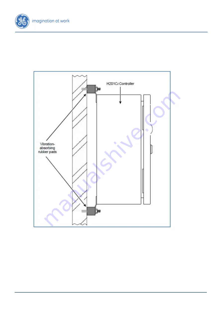
Vibration-Absorbing Rubber Pads 

If  vibrations  are  present,  rubber  pads  (which  can  be  purchased  from  General 

Electric) are used on the back of the Hydran 201C

i

 Controllers; an example is shown 

in Figure 3 below. 


Figure 3: Vibration-Absorbing Rubber Pads 

Summary of Contents for Hydran 201i

Page 1: ... GE Energy Lissue Industrial Estate East Lissue Road Lisburn BT28 2RE United Kingdom Tel 44 0 28 9262 2915 Fax 44 0 28 9262 2202 Email ge4service ge com Web www gedigitalenergy com md htm Hydran 201i System Installation Guide ...

Page 2: ...evisions 7 1 5 Standard GE Energy Warranty 8 2 GENERAL 10 2 1 Typical Installation 10 2 2 Preferred Locations 11 2 3 Vibration Absorbing Rubber Pads 14 3 GENERAL WARNINGS 15 4 BEFORE INSTALLATION 22 5 INSTALLATION 25 5 1 Tools and Materials Required 25 5 2 Verifying the AC Power Supply Voltage 25 5 3 Preparing the Hydran 201Ti 25 5 4 Installing the Brass Adaptor onto the Valve 27 5 5 Installing th...

Page 3: ...vées rigoureusement Tout écart par rapport à celles ci pourrait causer des dommages irréversibles au transformateur surveillé et ou au Hydran 201i et pourrait entraîner des dommages à la propriété des blessures corporelles et ou la mort L installation et l entretien du Hydran 201i doivent être effectués par du personnel qualifié seulement Veuillez aviser l opérateur du poste avant l entretien Trav...

Page 4: ...e vor der Wartung Das Arbeiten innerhalb des Hydran 201i kann aufgrund von Parameteränderungen Spannungsabschaltung Neubooten des Systems oder elektrostatischer Entladung unerwartete Alarme auslösen Für eine maximale Entfernung von 15 m von der Spannungsquelle verwenden Sie ein 2 08 mm2 Kabel 14 AWG und ein Überstromschutz 1 1 5 IT in Italian ATTENZIONE Tutte le procedure del presente manuale dovr...

Page 5: ...ver avstängning systemomstart eller elektrostatisk urladdning För ett maximalt avstånd på 15 m från kraftuttaget använd 2 08 mm2 kabel 14 AWG och ett överströmsskydd 1 2 Safety Symbols Description Description of safety symbols used on the Hydran M2 device Refer to the Instruction Manual to prevent injury or damage to equipment Hazardous voltages may be present Protective earth connection Descripti...

Page 6: ...ath Installation and maintenance of the Hydran 201i must be carried out by qualified personnel only Any visible signs of damage to the shipping packages should be reported to GE Energy immediately Please keep all documentation model number manuals etc for reference and warranty purposes A Table of Contents is present at the beginning of the manual The Hydran 201i Installation Guide this manual the...

Page 7: ...fy GE Energy in writing but not later than 30 days and make the Products available promptly for correction GE Energy shall thereupon correct any defect by at its option repairing the defective Products or making available necessary replacement parts Any failure which is the basis for a warranty claim shall not be cause for extension of the duration of the applicable Warranty Period GE Energy shall...

Page 8: ...re not normally supplied by GE Energy The preceding paragraphs set forth the exclusive remedies for all claims based on failure of or defect in Products covered by this manual whether the failure or defect arises before or during the applicable Warranty Period and whether a claim however instituted is based on contract indemnity warranty tort including negligence or civil liability strict liabilit...

Page 9: ...tallation Guide Page 10 17996 Rev5 August 2013 2 GENERAL 2 1 Typical Installation A typical installation of the Hydran 201i System is presented in Figure 1 below Figure 1 Typical Installation of the Hydran 201i System ...

Page 10: ...nt factors are proper location and installation of the H201Ti For a typical transformer the four most common locations to install the H201Ti are shown in Figure 2 1 Radiator s return pipe The recommended location to mount the H201Ti is on the straight section of the radiator s return pipe which is joining the bottom of the radiator to the transformer s main tank on the discharge side of the pump t...

Page 11: ...tting box The turbulent oil flow at these locations may result in inaccurate gas level readings 3 If the H201Ti is mounted directly on the wall of the transformer tank ensure it is installed below the oil level 4 No obstructions baffle pipe etc must exist behind the valve inside the tank 5 Regardless of the selected location it is recommended to mount the H201Ti horizontally If no horizontal valve...

Page 12: ...tion to a horizontal installation It is recommended to set the temperature set point Temp SetPoint parameter in the Temperature submenu of the H201 sensor to 45 C 113 F If these four recommended locations cannot be used contact General Electric Customer Service contact information can be found at the bottom of page 2 to help you determine an acceptable alternative location CAUTION ...

Page 13: ...t 2013 2 3 Vibration Absorbing Rubber Pads If vibrations are present rubber pads which can be purchased from General Electric are used on the back of the Hydran 201Ci Controllers an example is shown in Figure 3 below Figure 3 Vibration Absorbing Rubber Pads ...

Page 14: ... factory for a specific H201 sensor To verify whether the two components are paired correctly consult the serial numbers indicated on the shipping box and or the Test Certificate and Data Sheet The sensor s serial number is located below the connector see Figure 4 below while the H201Ti s serial number is located at the back of the heating plate see Figure 5 Figure 4 Hydran 201 Sensor and Protecti...

Page 15: ... and the sensor membrane from debris and sharp objects If the sensor is dismounted place immediately the supplied cap onto the sensor s threads Mishandling of the Hydran 201 sensor such as a perforation or scratch on the membrane or subjecting the sensor to paint or solvent voids the warranty 3 Do not touch the H201 sensor s membrane located inside the threaded extremity with a finger or an object...

Page 16: ...s voiding the warranty 5 Do not paint the sensor see Figure 7 below Paint fumes block the sensor s breathing membrane and damage the sensor permanently thus voiding the warranty 6 Do not use hydrocarbon based compounds near the sensor Do not clean the sensor with any solvent or other products see Figure 7 below The volatile fumes of these compounds can deteriorate sensor performances Products to a...

Page 17: ...t 7 Do not use a pipe wrench or chain wrench to install the sensor Doing so may cause serious damage to the sensor thus voiding the warranty It is recommended to use General Electric s Hydran 201TW tube wrench see Figure 8 below to correctly install the Hydran 201 sensor One Hydran 201TW tube wrench per site is recommended ...

Page 18: ...Page 19 Hydran 201i Installation Guide 17996 Rev5 August 2013 Figure 8 Use the Hydran 201TW instead of a Pipe Wrench ...

Page 19: ...igure 9 Do Not Install the H201Ti on the Inlet Side of the Radiator Pump 9 Do not use galvanized fittings to install the brass adaptor and the sensor Galvanized fittings pipes reducing bushings rings etc may react with the oil and produce elevated gas level readings Similarly do not use galvanized fittings on transformer valves used for oil sampling ...

Page 20: ...s level readings Figure 10 Do Not Install the H201Ti on an Elbow 11 Do not subject the H201Ti or its sensor to high pressure water streams see Figure 11 below Used during the cleaning of transformers they may cause serious damage Figure 11 Avoid High Pressure Water Streams 12 Do not punch additional openings in the H201Ci Controller s enclosure This enclosure already has openings for the various c...

Page 21: ...lly inspect the sensor membrane before installation on the valve Remove the protective plastic cap and look inside the opening The membrane s surface must be flat without cuts or tears Do not touch the H201 sensor s membrane for any reason 2 Use only PTFE tape to seal the threads of both the adapter and the Hydran 201 sensor Wrap at least 4 to 5 layers of tape around the threads Always wrap the ta...

Page 22: ...ure at this location must always be below 30 C 86 F It is recommended to set the temperature set point Temp SetPoint parameter in the Temperature submenu of the H201 sensor to 45 C 113 F Do not use a 90 elbow to convert a vertical installation to a horizontal installation 5 Always mount the H201 sensor on a full bore gate or ball valve where there is sufficient convective oil flow The H201Ti is in...

Page 23: ... times the nominal diameter of the valve 230mm 9 in for a 38mm 1 5in valve See Figure 14 below Figure 14 Maximum Distance between the Hydran 201Ti and the Valve 7 The H201Ti weighs 5 6kg 12lb If the selected valve is subject to strong vibrations install a supporting bracket to reduce the load on the valve In case of doubt consult your engineering personnel ...

Page 24: ...utputs and communications Digital voltmeter ammeter 5 2 Verifying the AC Power Supply Voltage Verify the following values are equivalent The ac power supply voltage which is indicated on the left side of the I O module The power source voltage The value on the Test Certificate and Data Sheet 5 3 Preparing the Hydran 201Ti 1 Unscrew the H201Ti s aluminum cover knob 2 Remove the cover 3 Remove only ...

Page 25: ...tic cap see Figure 7 Do not remove the protective plastic caps from the sensor and or brass adaptor s threaded extremity until ready to install on the transformer valve 9 Unscrew the sensor to separate it from the brass adapter Do not touch the H201 sensor s membrane for any reason 10 Inspect the sensor s membrane by looking at it Its surface must be flat without cuts or tears CAUTION CAUTION ...

Page 26: ... it using a pipe wrench Ensure two of the screw holes of the adaptor used to fasten the Hydran 201Ti s heating plate are level horizontal 5 5 Installing the Hydran 201 Sensor 1 Cover the adaptor s threads with PTFE tape see Figure 12 2 Slightly loosen the sensor s bleed screw using the supplied 5 32 in Allen key 3 Screw the sensor manually onto the adaptor 4 Tighten the sensor using General Electr...

Page 27: ...Use a bucket to collect the oil 1 Using the supplied 5 32 in Allen key fully close the sensor s bleed screw and then open it 1 8 of turn 2 Slowly open the transformer valve until oil leaks out of the sensor s sampling port see Figure 16 below Figure 16 Purging Air from the Hydran 201 Sensor 3 When there are no more air bubbles present in the oil shut the bleed screw tightly 4 Open the valve comple...

Page 28: ...Installation Guide 17996 Rev5 August 2013 5 Wipe all traces of oil from the sensor Do not use any solvent 6 Inspect the adaptor and sensor for oil leaks 7 Dispose of the collected oil according to company standards CAUTION ...

Page 29: ...to the Brass Adapter Be careful not to squeeze the nearby electrical wires between the lock washers and the heating plate or not to damage the supervisory link and analog output termination board Note When the H201Ti is installed horizontally the terminals must be facing up and located under the sensor Also ensure that both the bleed screw and sampling port remain easy to access 2 Plug the twist l...

Page 30: ...the conduits and or cable shields at some point Follow the company regulations meticulously The H201Ti must always be grounded even if the transformer tank is grounded at a single point and monitored for tank to ground currents 5 Run the supervisory link cable into the conduit up to the H201Ci Controller the electrical connections drawings can be found in APPENDIX A ELECTRICAL CONNECTIONS 6 Connec...

Page 31: ...upply cable into the second conduit up to the Hydran 201Ti 10 Connect the cable to the H201Ti s terminals L1 L L2 N and E G For wiring details see the electrical connections in APPENDIX A ELECTRICAL CONNECTIONS 11 Connect the other end of the cable to the power source Note The earth ground terminal E G must be connected to the power source ground green wire or directly to the transformer tank Neve...

Page 32: ...ntral post of the Hydran 201Ti until the connector at the back of the module is completely inserted in the mating connector 2 Fasten the module with the two 6 32 screws see Figure 18 below Figure 18 Installing the CPU Module When fastening the CPU module ensure not to bend the pins of the connector located between the CPU and I O modules CAUTION ...

Page 33: ...e LED must remain lit if the internal temperature is below the set point The LED must flash if the internal temperature is close to the set point The LED must remain off if the internal temperature exceeds the set point 5 Regulated 5 Vdc supply LED green It must be lit 5 Regulated 5 Vdc supply LED green It must be lit OK System state indicator LED green It must be lit HH High High alarm state LED ...

Page 34: ...enclosure temperature reaches the above set point o It must remain off if the ambient temperature exceeds the set point 6 If the H201Ti is linked to a Hydran 201Ci 1 Controller power them up and verify the H201Ci 1 s operation by observing the following LED s and indicators The Supervisory Link Supply indicator green DS12 is lit The Heater indicator yellow DS8 o It must initially be lit if the amb...

Page 35: ...Page 36 17996 Rev4 June 2013 Hydran 201i Installation Guide 6 APPENDIX A ELECTRICAL CONNECTIONS Figure 20 Electrical Connections for the Hydran 201Ti ...

Page 36: ...Hydran 201i Installation Guide Page 37 17996 Rev4 June 2013 Figure 21 Electrical Connections for the Hydran 201Ci C ...

Page 37: ...Page 38 17996 Rev4 June 2013 Hydran 201i Installation Guide Figure 22 Electrical Connections for the Hydran 201Ci 1 ...

Reviews: