background image


Chapter 2: Installation 

GE-DSH-73/DSH-82 and DSH-82-PoE User Manual 

17 

The top panel of the GE-DSH-73 Managed Industrial Switch has two terminal block 
connectors: 

• 

Power connector - consists of two DC power inputs and one fault alarm. 

• 

DI/DO connector - comprises two digital inputs-DI0 and DI1and two digital 
outputs-DO0 and DO1. 

Figure 2-9

:  

Top Panel of GE-DSH-73


Summary of Contents for GE-DSH-73

Page 1: ...GE Security P N 1069172 REV 1 0 ISS 22FEB10 GE DSH 73 DSH 82 DSH 82 PoE User Manual ...

Page 2: ...ine at www gesecurity com This product is intended to be supplied by a UL Listed Direct Plug In Power Unit marked Class 2 or LPS and output rated 48 VDC 380 mA minimum FCC compliance This equipment has been tested and found to comply with the limits for a Class A digital device pursuant to part 15 of the FCC Rules These limits are designed to provide reasonable protection against harmful interfere...

Page 3: ...m 46 Port Management 65 Protocol 76 Security 118 Digital Input Output GE DSH 73 129 Power Over Ethernet GE DSH 82 PoE 131 Factory Default 135 Save Configuration 135 System Reboot 136 Chapter 6 Command Sets 137 System Commands Set 137 Port Commands Set 140 Trunk Commands Set 142 VLAN Commands Set 143 Spanning Tree Commands Set 145 QOS Commands Set 147 IGMP Commands Set 148 MAC Filter Table Commands...

Page 4: ... Commands Set 160 PoE Command Set 161 Chapter 7 Switch Operation 163 Address Table 163 Chapter 8 Power Over Ethernet Overview 165 What is PoE 165 Appendix A RJ 45 Pin Assignment 171 Switch s RJ 45 Pin Assignments 171 10 100Mbps 10 100Base TX 172 Appendix B Troubleshooting 175 ...

Page 5: ...rts Ethernet Switches with Gigabit TP SFP fiber optical combo connective ability and robust layer 2 features The description of these models is below GE DSH 82 8 Port 10 100Base TX 2 Port Gigabit TP SFP Combo Managed Industrial Ethernet Switch GE DSH 82 PoE 8 Port 10 100Base TX 2 Port Gigabit TP SFP Combo Managed Industrial PoE Switch GE DSH 73 7 Port 10 100Base TX 3 Port Gigabit TP SFP Combo Mana...

Page 6: ...r Industrial Networks The GE Security GE DSH 82 series Managed Industrial Ethernet Switch with multiple redundant ring technology is equipped with 8 10 100Mbps Fast Ethernet ports and 2 Gigabit TP SFP combo interfaces and the GE DSH 73 is equipped with 7 10 100Mbps Fast Ethernet ports and 3 Gigabit TP SFP combo interfaces All of them are delivered in a rugged high strength case It is an industrial...

Page 7: ... which are usually found on plant floors or in curb side traffic control cabinets The GE DSH 82 GE DSH 73 series also provides a wide range of power supply options suitable for multiple industries and for worldwide operation The feature of operating temperature range from 40 to 75 Degree C allows the Managed Industrial Switch to be placed in almost any difficult environment Robust Layer 2 Features...

Page 8: ...ED PoE Status Monitoring Note The GE DSH 82 PoE PoE requires the use of the recommended external power source o GE DSH 73 7 Port 10 100Base TX RJ 45 3 Port 10 100 1000Base T TP combo interfaces 3 mini GBIC SFP slots shared with Gigabit copper ports and support 100 1000 Dual Mode 1 RJ 45 Console interface for Switch basic management and setup Industrial Conformance Wide range redundant power with p...

Page 9: ...5 VLANs groups out of 4K VLAN IDs o Supports Spanning Tree Protocol STP IEEE 802 1D Spanning Tree Protocol RSTP IEEE 802 1w Rapid Spanning Tree Protocol o Supports Link Aggregation Up to 4 Trunk groups Up to 4 ports per trunk group with 800Mbps bandwidth Full Duplex mode IEEE 802 3ad LACP Link Aggregation Control Protocol Cisco ether Channel Static Trunk Quality of Service o 4 priority queues on a...

Page 10: ...w switch to advise its identification and capability on the LAN Product Specifications Product GE DSH 82 GE DSH 82 PoE GE DSH 73 Hardware Specification 10 100Mbps Copper Ports 8 10 100Base TX RJ 45 Auto MDI MDI X ports 8 10 100Base TX RJ 45 Auto MDI MDI X ports 7 10 100Base TX RJ 45 Auto MDI MDI X ports 1000Mbps Copper Ports 2 10 100 1000Base T RJ 45 ports 2 10 100 1000Base T RJ 45 ports 3 10 100 ...

Page 11: ...Collision Yellow 2 SFP port LNK ACT Green 2 1000T LNK ACT Green 1000M Green PoE PoE In use Green Per unit Power Green Ring Master Green Power 1 Green Power 2 Green Fault Red 7 port 10 100 Link Activity Green Full duplex Collision Yellow 3 SFP port LNK ACT Green 3 1000T LNK ACT Green 1000M Green DI DO 2 Digital Input DI Level 0 30 2V Level 1 10 30V Max input current 8mA 2 Digital Output DO Open col...

Page 12: ...LAN ID up to 256 VLAN groups Spanning Tree IEEE 802 1d Spanning Tree IEEE 802 1w Rapid Spanning Tree Link Aggregation Static Port Trunk IEEE 802 3ad LACP Link Aggregation Control Protocol Supports 4groups of 4 Port trunk QoS Traffic classification based on Port Number 802 1Q Tag 802 1p priority IP DSCP TOS field in IP Packet IGMP Snooping v1 and v2 256 multicast groups and IGMP query Bandwidth Con...

Page 13: ... Compliance IEEE 802 3 10Base T IEEE 802 3u 100Base TX 100Base FX IEEE 802 3z Gigabit SX LX IEEE 802 3ab Gigabit 1000T IEEE 802 3x Flow Control and Back pressure IEEE 802 1d Spanning tree protocol IEEE 802 1w Rapid spanning tree protocol IEEE 802 1p Class of service IEEE 802 1Q VLAN Tagging IEEE 802 1x Port Authentication Network Control IEEE 802 3af Power over Ethernet GE DSH 82 PoE RFC 768 UDP R...

Page 14: ...Chapter 1 Introduction 10 GE DSH 73 DSH 82 and DSH 82 PoE User Manual ...

Page 15: ...E DSH 73 DSH 82 and DSH 82 PoE User Manual 11 Chapter 2 Installation Hardware Description Physical Dimensions GE DSH 82 W x D x H 2 83 x 4 13 x 5 98 72mm x 105mm x 152mm Figure 2 1 GE DSH 82 panel layout ...

Page 16: ... 73 DSH 82 and DSH 82 PoE User Manual GE DSH 82 PoE W x D x H 2 83 x 4 13 x 5 98 72mm x 105mm x 152mm Figure 2 2 GE DSH 82 PoE panel layout GE DSH 73 W x D x H 2 83 x 4 13 x 5 98 72mm x 105mm x 152mm Figure 2 3 GE DSH 73 panel layout ...

Page 17: ...and Rear Panel of GE DSH 82 1 Model Name 9 10 100 1000Base T port 2 System Power LED 10 1000Base SX LX SFP slot 3 Ring Master LED indicator 11 LED indicators for 1000Base SX LX ort 4 LED for power 1 input 12 6 Pin Terminal Block 5 LED for power 2 input 13 Ground Screw 6 FAULT LED indicator 14 Screw holes for Wall Mounting kit 7 RJ 45 type RS 232 Console 15 DIN Rail Kit 8 8 x 10 100Base TX port ...

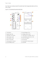
Page 18: ...PoE 1 Model Name 9 10 100 1000Base T port 2 System Power LED 10 1000Base SX LX SFP slot 3 Ring Master LED indicator 11 LED indicators for 1000Base SX LX ort 4 LED for power 1 input 12 LED indicators for PoE power output 5 LED for power 2 input 13 6 Pin Terminal Block 6 FAULT LED indicator 14 Ground Screw 7 RJ 45 type RS 232 Console 15 Screw holes for Wall Mounting kit 8 8 x 10 100Base TX port 16 D...

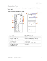
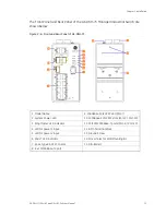
Page 19: ...DSH 73 1 Model Name 9 1000Base SX LX SFP slot Port 7 2 System Power LED 10 1000Base SX LX SFP slots Port 9 Port 10 3 Ring Master LED indicator 11 10 100 1000Base T ports Port 9 Port 10 4 LED for power 1 input 12 6 Pin Terminal Block 5 LED for power 2 input 13 Ground Screw 6 FAULT LED indicator 14 Screw holes for Wall Mounting kit 7 RJ 45 type RS 232 Console 15 DIN Rail Kit 8 8 x 10 100Base TX port...

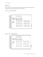
Page 20: ...2 and DSH 82 PoE User Manual Top View The top panel of the GE DSH 82 Managed Industrial Switch has one terminal block connector of two DC power inputs and one fault alarm Figure 2 7 Top Panel of GE DSH 82 Figure 2 8 Top Panel of GE DSH 82 PoE ...

Page 21: ...p panel of the GE DSH 73 Managed Industrial Switch has two terminal block connectors Power connector consists of two DC power inputs and one fault alarm DI DO connector comprises two digital inputs DI0 and DI1and two digital outputs DO0 and DO1 Figure 2 9 Top Panel of GE DSH 73 ...

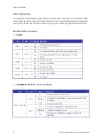
Page 22: ... On The industrial switch is the master of X Ring group R M Green Off The industrial switch is not a ring master in X Ring group On Power 1 is active PWR1 Green Off Power 1 is inactive On Power 2 is active PWR2 Green Off Power 2 is inactive On Power or port failure FAULT Red Off No failure 10 100Base TX Ports Port 1 to Port 8 LED Color Status Meaning On A network device is detected Blinking The po...

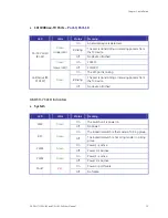
Page 23: ...P port is linking Blinking The port is transmitting or receiving packets from the TX device Link Active P9 P10 SFP Green Off No device attached GE DSH 73 LED Indicators System LED Color Status Meaning On The switch unit is power on PWR Green Off No power On The industrial switch is the master of X Ring group R M Green Off The industrial switch is not a ring master in X Ring group On Power 1 is act...

Page 24: ... Packets occurs Port 1 6 Port 8 Amber Off The port is in half duplex mode or no device is attached 10 100Base TX Ports Port 7 Port 9 and Port 10 LED Color Status Meaning On A network device is detected Blinking The port is transmitting or receiving packets from the TX device Green Upper LED Off No device attached On 1000M Port 7 Port 9 Port 10 RJ 45 Green Lower LED Off 10 100M On The SFP port is l...

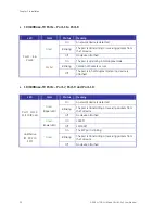
Page 25: ...Power 1 is active PWR1 Green Off Power 1 is inactive On Power 2 is active PWR2 Green Off Power 2 is inactive On Power or port failure FAULT Red Off No failure 10 100Base TX Ports Port 1 to Port 8 LED Color Status Meaning On A network device is detected Blinking The port is transmitting or receiving packets from the TX device Green Off No device attached On The port is operating in full duplex mode...

Page 26: ...hed 10 100 1000Base T SFP combo interface Port 9 Port 10 LED Color Status Meaning On A network device is detected Blinking The port is transmitting or receiving packets from the TX device Green Upper LED Off No device attached On 1000M Port 9 Port 10 RJ 45 Green Lower LED Off 10 100M On The SFP port is linking Blinking The port is transmitting or receiving packets from the TX device Link Active P9...

Page 27: ... section for wall mount plate installation 3 To hang the Industrial switch on the DIN Rail track or wall 4 Power on the Industrial switch Refer to the Wiring the Power Inputs section for knowing the information about how to wire the power The power LED on the Industrial switch will light up Please refer to the LED Indicators section for indication of LED lights 5 Prepare the twisted pair straight ...

Page 28: ...rial Switch when out of factory If the DIN Rail is not screwed on the Industrial Switch please see the following pictures to screw the DIN Rail on the Switch Follow the steps below to hang the Industrial Switch Figure 2 10 Rear Panel DIN Rail Kit 1 Insert the top of DIN Rail into the track Figure 2 11 Rear Panel DIN Rail Kit ...

Page 29: ...Plate Mounting Follow the steps below to mount the Industrial Switch with wall mount plate 1 Remove the DIN Rail from the Industrial Switch loose the screws to remove the DIN Rail 2 Place the wall mount plate on the rear panel of the Industrial Switch 3 Use the screws to screw the wall mount plate on the Industrial Switch 4 Use the hook holes at the corners of the wall mount plate to hang the Indu...

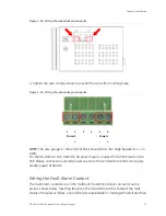
Page 30: ...anel of GE DSH 82 PoE is used for two DC redundant power inputs NOTE This product is intended to be supplied by a UL Listed Direct Plug In Power Unit marked Class 2 or LPS and output rated 48 VDC 380 mA minimum Please follow the steps below to insert the power wire 1 Insert the positive negative DC power wires into the contacts 1 and 2 for POWER 2 or 5 and 6 for POWER 1 ...

Page 31: ...ould be in the range between 12 24 AWG For the GE DSH 82 PoE A 48VDC 3A power input is required for full PoE load on the PoE Please connect an external power source to the terminal block that can supply steady power at 48VDC Wiring the Fault Alarm Contact The fault alarm contacts are in the middle of the terminal block connector as the picture shows below Inserting the wires the Industrial Switch ...

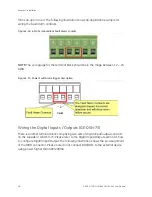
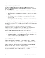
Page 32: ...n the range between 12 24 AWG Figure 2 17 Power Fault Alarm trigger description Wiring the Digital Inputs Outputs GE DSH 73 There is another terminal block comprising two sets of digital input output contacts on the topside of GE DSH 73 Please refer to the Digital Input Output section for how to configure Digital Input Output The following illustration shows the pin assignment of the DIDO connecto...

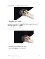
Page 33: ...ing the SFP transceiver The section describes how to insert an SFP transceiver into an SFP slot The SFP transceivers are hot pluggable and hot swappable You can plug in and out the transceiver to from any SFP port without having to power down the Industrial Switch Shown in Figure 2 19 Figure 2 19 Plug in the SFP transceiver ...

Page 34: ...es workstation or Media Converter 1 Make sure both side of the SFP transceiver are with the same media type for example 1000Base SX to 1000Base SX 1000Bas LX to 1000Base LX 2 Check the fiber optic cable type match the SFP transceiver model o To connect to 1000Base SX SFP transceiver use the Multi mode fiber cable with one side must be male duplex LC connector type o To connect to 1000Base LX SFP t...

Page 35: ... sure there is no network activity by consulting or checking with the network administrator or through the management interface of the switch converter if available to disable the port in advance 2 Remove the Fiber Optic Cable gently Figure 2 21 Pull out the SFP transceiver 3 Turn the handle of the MGB module horizontally 4 Pull out the module gently through the handle ...

Page 36: ...User Manual Figure 2 22 Pull out from the transceiver NOTE Never pull out the module without pull the handle or the push bolts on the module Pulling out the module with too much force could damage the module and SFP module slot of the Managed Industrial Switch ...

Page 37: ...E User Manual 33 Chapter 3 Network Application This chapter discusses how the Switches function in various Network environments A couple sample applications of the industrial switch are shown below Factory Redundant Ring Application ...

Page 38: ...Chapter 3 Network Application 34 GE DSH 73 DSH 82 and DSH 82 PoE User Manual Transportation Networking and Public Wireless Service ...

Page 39: ... Rapid Ring X Ring protocol that can help the network system to recovery from network connection failure within 20ms or less and make the network system more reliable The X Ring algorithm is similar to spanning tree protocol STP algorithm but its recovery time is faster than STP The following figure is a sample X Ring application ...

Page 40: ...The following figure is a sample of coupling ring application Dual Homing Application Dual Homing function is to prevent the connection lose from between X Ring group and upper level core switch Assign two ports to be the Dual Homing port that is backup port in the X Ring group The Dual Homing function only works when the X Ring function is active Each X Ring group only has one Dual Homing port NO...

Page 41: ...ach the end of RS 232 connector to PC or terminal and the other end of RJ 45 connector to the console port of the switch The connected terminal or PC must support the terminal emulation program Figure 4 1 RS 232 to RJ 45 cable DB9 RJ 45 Connector Pinouts DB9 PIN RJ 45 Connector 1 1 Orange White 2 2 Orange 3 3 Green White 4 4 Blue 5 5 Blue White 6 6 Green 7 7 Brown White 8 8 Brown 1 2 3 4 5 1 2 3 4...

Page 42: ...n connect the console port directly through PC without the need of Null Modem Figure 4 2 Connecting the Switch to a PC A terminal program is required to make the software connection to the GE DSH series Managed Industrial Switch Windows Hyper Terminal program is a good choice Hyper Terminal can be accessed from the Start menu 1 Click START then Programs Accessories and then Hyper Terminal When the...

Page 43: ...connected to the device power on the GE DSH series Managed Industrial Switch the terminal will display that it is running testing procedures 3 Then the following message asks the login password The factory default password as following and the login screen in below figure appears User name admin Password admin Figure 4 4 The login screen ...

Page 44: ...new password after this first setup Only enter commands in lowercase letters when in the console interface CLI Management The system supports the console management CLI command After you log in on to the system you will see a command prompt To enter CLI management interface type in enable command Figure 4 5 The CLI command interface ...

Page 45: ...vanced function status Save configuration Global Configuration Enter the configure command while in privileged EXEC mode switch config To exit to privileged EXEC mode enter exit or end Use this mode to configure those parameters that are going to be applied to your switch VLAN database Enter the vlan database command while in privileged EXEC mode switch vlan To exit to user EXEC mode enter exit Us...

Page 46: ...Chapter 4 Console Management 42 GE DSH 73 DSH 82 and DSH 82 PoE User Manual ...

Page 47: ...ockets The user has to explicitly modify the browser setting to enable Java Applets to use network ports The Managed Industrial Switch can be configured through an Ethernet connection make sure the manager PC must be set on same the IP subnet address with the Managed Industrial Switch For example the default IP address of the Managed Industrial Switch is 192 168 0 100 then the manager PC should be...

Page 48: ...VA runtime environment Plug in NOTE We recommend using Internet Explorer 6 0 or above to access GE DSH series Managed Industrial Switch Logging on the Switch 1 Use Internet Explorer 6 0 or above Web browser Enter the factory default IP address to access the Web interface The factory default IP Address as following http 192 168 0 100 2 When the following login screen appears please enter the defaul...

Page 49: ...5 2 Default main page 4 The Switch Menu on the left of the Web page let you access all the commands and statistics the Switch provides Now you can use the Web management interface to continue the switch management or manage the Managed Industrial Switch by Web interface The Switch Menu on the left of the web page let you access all the commands and statistics the Managed Industrial Switch provides...

Page 50: ...m Information Provides basic system description including contact information IP Configuration Sets the IP address for management access DHCP Server Configure the Switch as a DHCP server for assigning dynamic IP addresses to devices on a network TFTP Upgrade the firmware via TFTP server Save view the switch configuration to remote host Upload the switch configuration from remote host Fault Relay A...

Page 51: ...5 3 Switch settings interface This page includes the following fields Object Description System Name Assign the system name of the switch The maximum length is 64 bytes System Description Describes the switch System Location Assign the switch physical location The maximum length is 64 bytes System Contact Enter the name of contact person or organization Firmware Version Displays the switch s firmw...

Page 52: ...popup dialog shows up to inform the user that when the DHCP client is enabled the current IP will lose and user should find the new IP on the DHCP server IP Address Assign the IP address that the network is using If DHCP client function is enabled this switch is configured as a DHCP client The network DHCP server will assign the IP address to the switch and display it in this column The default IP...

Page 53: ...ssing simplifies network administration because the software keeps track of IP addresses rather than requiring an administrator to manage the task This means that a new computer can be added to a network without the hassle of manually assigning it a unique IP address The system provides the DHCP server function Having enabled the DHCP server function the switch system will be configured as a DHCP ...

Page 54: ...mple dynamic IP is in the range between 192 168 0 101 192 168 0 200 In contrast 192 168 0 200 is the High IP address Subnet Mask Type in the subnet mask of the IP configuration Gateway Type in the IP address of the gateway in your network DNS Type in the Domain Name Server IP Address in your network Lease Time sec It is the time period that system will reset the dynamic IP assignment to ensure the...

Page 55: ...pe Specifies the Type of Binding Dynamic Manual Lease Specifies the Lease time left in seconds Port and IP Bindings Assign the dynamic IP address bound with the port to the connected client The user is allowed to fill each port column with one particular IP address When the device is connecting to the port and asks for IP assigning the system will assign the IP address bound with the port Figure 5...

Page 56: ...oad a file from specified TFTP server to the Managed Industrial Switch Figure 5 8 Update Firmware interface This page includes the following fields Object Description TFTP Server IP Address Type in your TFTP server IP Firmware File Name Type in the name of the firmware image file to be updated Restore Configuration You can restore a previous backup configuration from the TFTP server to recover the...

Page 57: ...er IP Address Type in the TFTP server IP Restore File Name Type in the correct file name for restoring Backup Configuration You can back up the current configuration from flash ROM to the TFTP server for the purpose of recovering the configuration later It helps you to avoid wasting time on configuring the settings by backing up the configuration Figure 5 10 Backup Configuration interface ...

Page 58: ...event log will be sent to client only server only or both client and server What kind of event log will be issued to the client server depends on the selection on the Event Configuration tab There are five types of event available to be issued as the event log Device Cold Start Device Warm Start Authentication Failure X Ring Topology Change Port Event Syslog Configuration The System Logs enable vi...

Page 59: ...er Only or Both Client Only the system event log will only be sent to this interface of the switch Server Only the system log will only be sent to the remote system log server with its IP assigned Both the system event log will be sent to the remote server and this interface System Log Server IP Address When the Syslog Mode item is set as Server Only Both the user has to assign the system log serv...

Page 60: ...he e mail alert Besides this function provides the authentication mechanism including an authentication step through which the client effectively logs in to the SMTP server during the process of sending e mail alert Figure 5 12 SMTP Configuration interface This page includes the following fields Object Description Email Alert With this function being enabled the user is allowed to configure the de...

Page 61: ...ing email account on the mail server Password Type in the password for the email account Confirm Password Reconfirm the password Rcpt e mail Address 1 6 You can also fill each of the column fields with up to 6 e mail accounts to receive the email alert System Event Log Event Configuration Having ticked the Syslog SMTP checkboxes the event log email alert will be sent to the system log server and t...

Page 62: ...Failure When the SNMP authentication fails the system will issue the event log email alert to the system log SMTP server respectively X ring topology change When the X ring topology has changed the system will issue the event log email alert to the system log SMTP server respectively Port event selection Also before the drop down menu items are available the Syslog Client Mode selection item on th...

Page 63: ...rt Link Down Broken detection the FAULT LED indicator will light up when the port failure occurs certainly the check box beside the port must be ticked first Please refer to the segment of Wiring the Fault Alarm Contact for the failure detection Figure 5 14 Fault Relay Alarm interface This page includes the following fields Object Description Power Failure Tick the check box to enable the function...

Page 64: ... each participating subnet peer Daylight saving time DST is the convention of advancing clocks so that afternoons have more daylight and mornings have less Typically clocks are adjusted forward one hour near the start of spring and are adjusted backward in autumn Figure 5 15 SNTP Configuration interface This page includes the following fields Object Description SNTP Client Enable disable SNTP func...

Page 65: ...here Daylight Saving Period Set up the Daylight Saving beginning date time and Daylight Saving ending date time Please key in the value in the format of YYYYMMDD and HH MM leave a space between YYYYMMDD and HH MM YYYYMMDD an eight digit year month day specification HH MM a five digit including a colon mark hour minute specification For example key in 20070701 02 00 and 20071104 02 04 in the two co...

Page 66: ...ountain Daylight 6 hours 6 am MST Mountain Standard PDT Pacific Daylight 7 hours 5 am PST Pacific Standard ADT Alaskan Daylight 8 hours 4 am ALA Alaskan Standard 9 hours 3 am HAW Hawaiian Standard 10 hours 2 am Nome Alaska 11 hours 1 am CET Central European FWT French Winter MET Middle European MEWT Middle European Winter SWT Swedish Winter 1 hour 1 pm EET Eastern European USSR Zone 1 2 hours 2 pm...

Page 67: ...rs 10 pm IDLE International Date Line NZST New Zealand Standard NZT New Zealand 12 hours Midnight IP Security IP security function allows the user to assign 10 specific IP addresses that have permission to manage the switch through the http and telnet services for the securing switch management The purpose of giving the limited IP addresses permission is to allow only the authorized personnel devi...

Page 68: ...is switch via HTTP service Enable Telnet Server Having ticked this checkbox the devices whose IP addresses match any one of the ten IP addresses in the Security IP1 IP10 table will be given the permission to access this switch via telnet service Security IP 1 10 The system allows the user to assign up to 10 specific IP addresses for access security Only these 10 IP addresses can access and manage ...

Page 69: ... the new password The default is admin Confirm password Re type the new password Port Management Port Statistics The following chart provides the current statistic information which displays the real time packet transfer status for each port The user might use the information to plan and implement the network or check and find the problem when the collision or heavy traffic occurs Figure 5 18 Port...

Page 70: ...ize less than 64 octets oversize CRC Align errors fragments and jabbers packets via this port Rx Good Packet The counts of receiving good packets via this port Rx Bad Packet The counts of receiving good packets including undersize less than 64 octets oversize CRC error fragments and jabbers via this port Tx Abort Packet The aborted packet while transmitting Packet Collision The counts of collision...

Page 71: ...orce When the Negotiation column is set as Auto this column is read only Duplex It is available for selecting when the Negotiation column is set as Force When the Negotiation column is set as Auto this column is read only Flow Control Whether or not the receiving node sends feedback to the sending node is determined by this item When enabled once the device exceeds the input data rate of another d...

Page 72: ... of any one single port or network cable Link Aggregation Control Protocol LACP which is a protocol running on layer 2 provides a standardized means in accordance with IEEE 802 3ad to bundle several physical ports together to form a single logical channel All the ports within the logical channel or so called logical aggregator work at the same connection speed and LACP operation requires full dupl...

Page 73: ...est priority and is selected as the active LACP peer of the trunk group Group ID There are 13 trunk groups to be selected Assign the Group ID to the trunk group LACP When enabled the trunk group is using LACP A port which joins an LACP trunk group has to make an agreement with its member ports first Please notice that a trunk group including member ports split between two switches has to enable th...

Page 74: ...he exceed ports are standby redundant ports and can be aggregated if working ports fail If it is a static trunk group non LACP the number of work ports must equal the total number of group member ports Aggregator Information When you have setup the LACP aggregator you will see relavent information in here LACP disabled Having set up the aggregator setting with LACP disabled you will see the local ...

Page 75: ...lays the members of this static trunk group LACP enabled Having set up the aggregator setting with LACP enabled you will see the trunking group information between two switches on the tab of Aggregator Information o Switch 1 configuration 1 Set System Priority of the trunk group The default is 1 2 Select a trunk group ID by pull down the drop down menu bar 3 Enable LACP 4 Include the member ports ...

Page 76: ... configuration 6 Set System Priority of the trunk group For example 32768 7 Select a trunk group ID by pull down the drop down menu bar 8 Enable LACP 9 Include the member ports by clicking the Add button after selecting the port number and the column field of Work Ports changes automatically Figure 5 24 Switch 2 configuration interface 10 Click on the tab of Aggregator Information to check the tru...

Page 77: ...k group You can tick or cancel the checkbox beside the state label When you remove the tick mark of the port and click APPLY the port state activity will change to Passive Figure 5 26 State Activity of Switch 1 This page includes the following fields Object Description Active The port automatically sends LACP protocol packets Passive The port does not automatically send LACP protocol packets and r...

Page 78: ...trunk because both ports are waiting for an LACP protocol packet from the opposite device Port Mirroring The Port mirroring is a method for monitor traffic in switched networks Traffic through ports can be monitored by one specific port which means traffic goes in or out monitored source ports will be duplicated into mirror destination port Figure 5 28 Port Trunk Port Mirroring interface ...

Page 79: ...ray Source Port The ports that user wants to monitor All monitored port traffic will be copied to mirror destination port User can select multiple source ports by checking the RX or TX check boxes to be monitored Rate Limiting You can set up every port s bandwidth rate and frame limitation type Ingress Limit Frame type select the frame type that wants to filter There are four frame types for selec...

Page 80: ...t s effective egress rate is 1Mbps ingress rate is 500Kbps The switch performs the ingress rate by packet counter to meet the specified rate o Ingress Enter the port effective ingress rate The default value is 0 o Egress Enter the port effective egress rate The default value is 0 And then click APPLY to apply the settings Protocol This section has the following items VLAN Rapid Spanning Tree proto...

Page 81: ...e same segment communications take place using normal Ethernet protocols Even though this is always the case when the destination for a packet lies on another switch port VLAN considerations come into play to decide if the packet is dropped by the Switch or delivered IEEE 802 1Q VLANs IEEE 802 1Q tagged VLAN are implemented on the Switch 802 1Q VLAN require tagging which enables them to span the e...

Page 82: ...ity are used by 802 1p The VID is the VLAN identifier and is used by the 802 1Q standard Because the VID is 12 bits long 4094 unique VLAN can be identified The tag is inserted into the packet header making the entire packet longer by 4 octets All of the information originally contained in the packet is retained 802 1Q Tag User Priority CFI VLAN ID VID 3 bits 1 bits 12 bits TPID Tag Protocol Identi...

Page 83: ...are different the switch will drop the packet Because of the existence of the PVID for untagged packets and the VID for tagged packets tag aware and tag unaware network devices can coexist on the same network A switch port can have only one PVID but can have as many VID as the switch has memory in its VLAN table to store them Because some devices on a network may be tag unaware a decision must be ...

Page 84: ...5 30 VLAN Configuration interface Port based VLAN A port based VLAN basically consists of its members ports which means that the VLAN is created by grouping the selected ports This method provides the convenience for users to configure a simple VLAN easily without complicated steps Packets can go among only members of the same VLAN group Note all unselected ports are treated as belonging to anothe...

Page 85: ...in Port Based mode Click ADD to add a new VLAN group The maximum VLAN groups are up to 64 Figure 5 32 VLAN Port Based Add interface Enter the group name and VLAN ID Add the selected port number into the right field to group these members to be a VLAN group or remove any of them listed in the right field from the VLAN And then click APPLY to have the configuration take effect You will see the VLAN ...

Page 86: ...ers of the same broadcast domain The valid VLAN ID is in the range of number between 1 and 4094 The amount of VLAN groups is up to 256 including default VLAN that cannot be deleted Each member port of 802 1Q is on either an Access Link no VLAN tagged or a Trunk Link VLAN tagged KK1 All frames on an Access Link carry no VLAN identification Conversely all frames on a Trunk Link are VLAN tagged Besid...

Page 87: ...l not alter the packet Thus all packets received by and forwarded by an untagging port will have no 802 1Q VLAN information Remember that the PVID is only used internally within the Switch Untagging is used to send packets from an 802 1Q compliant network device to a non compliant network device Frame Income Frame Leave Income Frame is tagged Income Frame is untagged Leave port is tagged Frame rem...

Page 88: ...t out of those ports Port Mode VLAN Membership Frame Leave Access Link Belongs to a single untagged VLAN Untagged Tag PVID be removed Trunk Link Allowed to belongs to multiple Tagged VLANs at the same time Tagged Tag PVID or Original VID be remained Hybrid Link Allowed to belongs to multiple untagged VLANs at the same time Untagged by specify VID The 802 1Q VLAN Port Configuration screen is shown ...

Page 89: ... link type Access Link A segment which provides the link path for one or more stations to the VLAN aware device An Access Port untagged port connected to the access link has an untagged VID also called PVID After an untagged frame gets into the access port the switch will insert a four byte tag in the frame The contents of the last 12 bit of the tag is untagged VID When this frame is sent out thro...

Page 90: ...e 2 It s not necessary to type 1 in the tagged VID The trunk port will forward the frames of VLAN 1 3 The trunk port has to be connected to a trunk hybrid port of the other switch Both the tagged VID of the two ports have to be the same NOTE Hybrid Link 1 It s not necessary to type 1 in the tagged VID The hybrid port will forward the frames of VLAN 1 2 The trunk port has to be connected to a trunk...

Page 91: ...ment GE DSH 73 DSH 82 and DSH 82 PoE User Manual 87 Figure 5 35 802 1Q VLAN interface Group Configuration Edit the existing VLAN Group Select the VLAN group in the table list Click EDIT Figure 5 36 Group Configuration interface ...

Page 92: ... provide backup links between switches bridges or routers This allows the switch to interact with other bridging devices in your network to ensure that only one route exists between any two stations on the network and provide backup links which automatically take over when a primary link goes down The spanning tree algorithms supported by this switch include these versions STP Spanning Tree Protoc...

Page 93: ...nts Creates multiple spanning trees from any combination of ports contained within a single switch in user specified groups Automatically reconfigures the spanning tree to compensate for the failure addition or removal of any element in the tree Reconfigures the spanning tree without operator intervention Bridge Protocol Data Units For STP to arrive at a stable network topology the following infor...

Page 94: ...number than the current root port can cause a root port change STP Port States The BPDUs take some time to pass through a network This propagation delay can result in topology changes where a port that transitioned directly from a Blocking state to a Forwarding state could create temporary data loops Ports must wait for new network topology information to propagate throughout the network before st...

Page 95: ...ng to disabled From disabled to blocking Figure 5 38 STP Port State Transitions You can modify each port state by using management software When you enable STP every port on every switch in the network goes through the blocking state and then transitions through the states of listening and learning at power up If properly configured each port stabilizes to the forwarding or blocking state No packe...

Page 96: ...itch level Parameter Description Default Value Bridge Identifier Not user configurable except by setting priority below A combination of the User set priority and the switch s MAC address The Bridge Identifier consists of two parts a 16 bit priority and a 48 bit Ethernet MAC address 32768 MAC 32768 MAC Priority A relative priority for each switch lower numbers give a higher priority and a greater ...

Page 97: ... Value Enable state STP disabled for all ports Port priority 128 Port cost 0 Bridge Priority 32 768 User Changeable STA Parameters The Switch s factory default setting should cover the majority of installations However it is advisable to keep the default settings as set at the factory unless it is absolutely necessary The user changeable parameters in the Switch are as follows Priority A Priority ...

Page 98: ... Port Cost can be set from 0 to 200000000 The lower the number the greater the probability the port will be chosen to forward packets Illustration of STP A simple illustration of three switches connected in a loop is depicted in the below diagram In this example you can anticipate some major network problems if the STP assistance is not applied If switch A broadcasts a packet to switch B switch B ...

Page 99: ...ity setting or influencing STP to choose a particular port to block using the Port Priority and Port Cost settings is however relatively straight forward Figure 5 39 Before Applying the STA Rules In this example only the default STP values are used Figure 5 40 After Applying the STA Rules ...

Page 100: ...redundant link between switch B and C is deliberately chosen as a 100 Mbps Fast Ethernet link default port cost 19 Gigabit ports could be used but the port cost should be increased from the default to ensure that the link between switch B and switch C is the blocked link RSTP System Configuration This section provides RSTP System Configuration from the Switch the screen in Figure 5 41 appears The ...

Page 101: ...er a value between 6 through 40 Hello Time 1 10 The time that controls the switch to send out the BPDU packet to check RSTP current status Enter a value between 1 through 10 Forward Delay Time 4 30 The number of seconds a port waits before changing from its Rapid Spanning Tree Protocol learning and listening states to the forwarding state Enter a value between 4 through 30 NOTE Follow the rule as ...

Page 102: ...ned can only be connected to exactly another bridge i e it is served by a point to point LAN segment or can be connected to two or more bridges i e it is served by a shared medium LAN segment This function allows the P2P status of the link to be manipulated administratively True means the port is regarded as a point to point link False means the port is regarded as a shared link Auto means the lin...

Page 103: ...rnet 10 60 20 000 2 000 000 Gigabit Ethernet 3 10 2 000 200 000 Table 5 2 Recommended STP Path Costs Port Type Link Type IEEE 802 1D 1998 IEEE 802 1w 2001 Ethernet Half Duplex Full Duplex Trunk 100 95 90 2 000 000 1 999 999 1 000 000 Fast Ethernet Half Duplex Full Duplex Trunk 19 18 15 200 000 100 000 50 000 Gigabit Ethernet Full Duplex Trunk 4 3 10 000 5 000 SNMP Configuration Simple Network Mana...

Page 104: ...ect information and to set MIB objects Click APPLY To remove the community string select the community string that you defined before and click REMOVE The strings of Public_RO and Private_RW are default strings You can remove them but after resetting the switch to default the two strings show up again Agent Mode Select the SNMP version that you want to use it And then click CHANGE to switch to the...

Page 105: ...e includes the following fields Object Description IP Address Enter the IP address of the trap manager Community Enter the community string for the trap station Trap Version Select the SNMP trap version type v1 or v2c SNMPV3 Configuration Configure the SNMP V3 function Figure 5 45 SNMP V3 configuration interface User Table ...

Page 106: ...ontext name Click REMOVE to remove unwanted context name User Table Configure SNMP v3 user table This page includes the following fields Object Description User ID Set up the user name Authentication Password Set up the authentication password Privacy Password Set up the private password Group Table Configure SNMP v3 group table Figure 5 46 SNMP V3 configuration interface Group Table ...

Page 107: ...group name Access Table Configure SNMP v3 access table Figure 5 47 SNMP V3 configuration interface Access Table This page includes the following fields Object Description Context Prefix Set up the context name Group Name Set up the group Security Level Select the access level Context Match Rule Select the context match rule Read View Name Set up the read view Write View Name Set up the write view ...

Page 108: ...oE User Manual MIBview Table Configure MIB view table Figure 5 48 SNMP V3 configuration interface MIBView Table This page includes the following fields Object Description ViewName Set up the name Sub Oid Tree Fill the Sub OID Type Select the type exclude or included ...

Page 109: ...priorities to traffic for example to set higher priorities to time critical or business critical applications Applying security policy through traffic filtering Provide predictable throughput for multimedia applications such as video conferencing or voice over IP by minimizing delay and jitter Improve performance for specific types of traffic and preserve performance as the amount of traffic grows...

Page 110: ...t fair queue scheme The switch will follow 8 4 2 1 rate to process priority queue from High to lowest queue For example while the system processing 1 frame of the lowest queue 2 frames of the low queue 4 frames of the middle queue and 8 frames of the high queue will be processed at the same time in accordance with the 8 4 2 1 policy rule Use a strict priority scheme Always the higher queue will be...

Page 111: ...h port Figure 5 50 QoS Configuration Port Based Priority This page includes the following fields Object Description Port x Each port has 4 priority levels High Middle Low and Lowest to be chosen COS Configuration QoS settings allow customization of packet priority in order to facilitate delivery of data traffic that might be affected by latency problems When CoS 802 1p Tag Priority is applied the ...

Page 112: ...tes Set up the COS priority level With the drop down selection item of Priority Type above being selected as COS only COS first this control item will then be available to set the queuing policy for each port Figure 5 52 QoS Configuration COS Priority This page includes the following fields Object Description COS priority Set up the COS priority level 0 7 High Middle Low Lowest NOTE 802 1p Priorit...

Page 113: ... as the Figure 5 53 shows Set up the TOS priority With the drop down selection item of Priority Type above being selected as TOS only TOS first this control item will then be available to set the queuing policy for each port Figure 5 53 QoS Configuration TOS Priority This page includes the following fields Object Description TOS priority The system provides 0 63 TOS priority level Each level has 4...

Page 114: ...inform nearby routers that they will become members of a multicast group The Internet Group Management Protocol IGMP is used to communicate this information IGMP is also used to periodically check the multicast group for members that are no longer active In the case where there is more than one multicast router on a sub network one router is elected as the queried This router then keeps track of t...

Page 115: ...Chapter 5 Web Based Management GE DSH 73 DSH 82 and DSH 82 PoE User Manual 111 Figure 5 55 Multicast flooding Figure 5 56 IGMP Snooping multicast stream control ...

Page 116: ...Report version 2 0x17 Leave a Group version 2 0x12 Membership Report version 1 IGMP packets enable multicast routers to keep track of the membership of multicast groups on their respective sub networks The following outlines what is communicated between a multicast router and a multicast group member using IGMP A host sends an IGMP report to join a group A host will never send a report when it wan...

Page 117: ... is more than one router switch on the LAN performing IP multicasting one of these devices is elected querier and assumes the role of querying the LAN for group members It then propagates the service requests on to any upstream multicast switch router to ensure that it will continue to receive the multicast service NOTE Multicast routers use this information along with a multicast routing protocol...

Page 118: ... in the ring Only one switch in the X Ring group would be set as the master switch that one of its two member ports would be blocked called backup port and another port is called working port Other switches in the X Ring group are called working switches and their two member ports are called working ports When the failure of network connection occurs the backup port of the master switch Ring Maste...

Page 119: ... X Ring Application In the network it may have more than one X Ring group By using the coupling ring function it can connect each X Ring for the redundant backup It can ensure the transmissions between two ring groups not to fail The following figure is a sample of coupling ring application ...

Page 120: ...een X Ring group and upper level core switch Assign two ports to be the Dual Homing port that is backup port in the X Ring group The Dual Homing function only works when the X Ring function is active Each X Ring group only has one Dual Homing port Figure 5 61 Dual Homing Ring Application NOTE In Dual Homing application architecture the upper level switches need to enable the Rapid Spanning Tree pr...

Page 121: ... user can identify whether the switch is the ring master by checking the R M LED indicator on the panel of the Switch The system also supports the Couple Ring that can connect 2 or more X Ring group for the redundant backup function Dual Homing function that can prevent connection lose between X Ring group and upper level core switch Figure 5 62 X Ring Interface This page includes the following fi...

Page 122: ... when the X Ring function enabled NOTE When the X Ring function enabled the user must disable the RSTP The X Ring function and RSTP function cannot exist on a switch at the same time Remember to execute the Save Configuration action otherwise the new configuration will lose when switch powers off Security The Security page has the following settings 802 1x Radius Static MAC address MAC filter Secu...

Page 123: ...es Device Roles With 802 1X port based authentication the devices in the network have specific roles as shown below Figure 5 63 802 1x device role Client the device workstation that requests access to the LAN and switch services and responds to requests from the switch The workstation must be running 802 1X compliant client software such as that offered in the Microsoft Windows XP operating system...

Page 124: ...he switch receives frames from the authentication server the server s frame header is removed leaving the EAP frame which is then encapsulated for Ethernet and sent to the client Authentication Initiation and Message Exchange The switch or the client can initiate authentication If you enable authentication on a port by using the dot1x port control auto interface configuration command the switch mu...

Page 125: ...States The switch port state determines whether or not the client is granted access to the network The port starts in the unauthorized state While in this state the port disallows all ingress and egress traffic except for 802 1X protocol packets When a client is successfully authenticated the port transitions to the authorized state allowing all traffic for the client to flow normally If a client ...

Page 126: ... from the authenticated client are allowed through the port If the authentication fails the port remains in the unauthorized state but authentication can be retried If the authentication server cannot be reached the switch can retransmit the request If no response is received from the server after the specified number of attempts authentication fails and network access is not granted When a client...

Page 127: ...ied RADIUS Server Accounting Port Set the UDP destination port for accounting requests to the specified RADIUS Server Shared Key Set an encryption key for using during authentication sessions with the specified RADIUS server This key must match the encryption key used on the RADIUS Server NAS Identifier Set the identifier for the RADIUS client Port Configuration You can configure the 802 1x authen...

Page 128: ...orized state Authorize The specified port is set to the Authorized or Unauthorized state in accordance with the outcome of an authentication exchange between the Supplicant and the authentication server Disable When disabled the specified port works without complying with 802 1x protocol Port Configuration You can configure the 802 1x authentication state for each port The state provides Disable A...

Page 129: ...sts Set the number of authentication that must time out before authentication fails and the authentication session ends Reauth period Set the period of time which clients connected must be re authenticated MAC Address Table Use the MAC address table to ensure the port security Static MAC Address You can add a static MAC address that remains in the switch s address table regardless of whether the d...

Page 130: ... 5 68 Static MAC Addresses interface This page includes the following fields Object Description MAC Address Enter the MAC address of the port that should permanently forward traffic regardless of the device network activity Port No Pull down the selection menu to select the port number ...

Page 131: ...ure 5 69 MAC Filtering interface This page includes the following fields Object Description MAC Address Enter the MAC address that you want to filter All MAC Addresses You can view all of the MAC addresses learned by the selected port Select the port number The selected port of static dynamic MAC address information will be displayed in here Click CLEAR MAC TABLE to clear the dynamic MAC addresses...

Page 132: ...onnected ports had been included in the specific multicast groups With multicast filtering network devices only forward multicast traffic to the ports that are connected to the registered end stations Figure 5 71 Multicast Filtering interface This page includes the following fields Object Description IP Address Assign a multicast group IP address in the range of 224 0 0 0 239 255 255 255 Member Po...

Page 133: ...xternal device like alarm buzzer or LED to inform the user of the port power status Digital Input When First Second Digital Input function is enabled First Digital Input Second Digital Input will then be available respectively Digital Input Choose the transition type to trigger DI0 DI1 o Low High Having focused this radio button DI0 DI1 will only report the status when the external device s voltag...

Page 134: ...he output type of electrical signal o Low High Having focused this radio button DO0 DO1 will output an electrical signal of Low to High when the condition of the ticked checkbox is met port power failure occurs o High Low Having focused this radio button DO0 DO1 will output an electrical signal of Low to High when the condition of the ticked checkbox is met port power failure occurs Figure 5 73 Di...

Page 135: ...ect Plug In Power Unit marked Class 2 or LPS and output rated 48 VDC 380 mA minimum Power over Ethernet Powered Device 3 5 watts Voice over IP phones Enterprise can install POE VoIP Phone ATA and other Ethernet non Ethernet end devices to the central where UPS is installed for un interrupt power system and power control system 6 12 watts Wireless LAN Access Points Museum Sightseeing Airport Hotel ...

Page 136: ...gement is implemented The PSU input power consumption is monitored by measuring voltage and current The input power consumption is equal to the system s aggregated power consumption The power management concept allows all ports to be active and activates additional ports as long as the aggregated power of the system is lower than the power level at which additional PDs cannot be connected When thi...

Page 137: ...apacitive Detection If the port and capacitive detection are enabled the capacitances state reads in the voltage result from the constant current This is then subtracted from the pre capacitance voltage to get a charge rate If this charge rate is within the window of the PD signatures the device is considered to be discovered Start Showing with a tick symbol the system initializes and resets succe...

Page 138: ...n provided by the PD The intent of PD classification is to provide information about the maximum power required by the PD during operation Class 0 is the default for PDs However to improve power management at the PSE the PD may opt to provide a signature for Class 1 to 3 The PD is classified based on power The classification of the PD is the maximum power that the PD will draw across all input vol...

Page 139: ...tion Click to reset all configurations to the default value Figure 5 75 Factory Default interface Save Configuration Save all configurations that you have made in the system To ensure the all configuration will be saved Click SAVE to save the all configuration information to flash memory Figure 5 76 Save Configuration interface ...

Page 140: ...hapter 5 Web Based Management 136 GE DSH 73 DSH 82 and DSH 82 PoE User Manual System Reboot Reboots the switch with a software reset Click REBOOT to reboot the system Figure 5 77 System Reboot interface ...

Page 141: ...on string switch config system location xxx system description System Description G Set switch system description string switch config system description xxx system contact System Contact G Set switch system contact window string switch config system contact xxx show system info E Show system information switch show system info ip address Ip address Subnet mask Gateway G Configure the IP address o...

Page 142: ...switch config dhcpserver subnetmask 255 255 255 0 dhcpserver gateway Gateway G Configure gateway for DHCP clients switch config dhcpserver gateway 192 168 1 254 dhcpserver dnsip DNS IP G Configure DNS IP for DHCP clients switch config dhcpserver dnsip 192 168 1 1 dhcpserver leasetime Hours G Configure lease time in hour switch config dhcpserver leasetime 1 dhcpserver ipbinding IP address I Set sta...

Page 143: ...ity list switch config security ip 1 192 168 1 55 show security P Show the information of IP security switch show security no security G Disable IP security function switch config no security no security http G Disable IP security of HTTP server switch config no security http no security telnet G Disable IP security of telnet server switch config no security telnet ...

Page 144: ...ecurity of interface switch config interface fastEthernet 2 switch config if no security bandwidth type all I Set interface ingress limit frame type to accept all frame switch config interface fastEthernet 2 switch config if bandwidth type all bandwidth type broadcast multicast flooded unicast I Set interface ingress limit frame type to accept broadcast multicast and flooded unicast frame switch c...

Page 145: ...ion command to specify the state mode of operation for Ethernet ports Use the disable form of this command to disable the port switch config interface fastEthernet 2 switch config if state Disable show interface configuration I show interface configuration status switch config interface fastEthernet 2 switch config if show interface configuration show interface status I show interface actual statu...

Page 146: ...e could not be less than zero or be large than the amount of member ports switch config aggregator group 1 1 4 lacp workp 2 or switch config aggregator group 2 1 4 3 lacp workp 3 aggregator group GroupID Port list nolacp G Assign a static trunk group GroupID 1 3 Port list Member port list This parameter could be a port range ex 1 4 or a port list separate by a comma ex 2 3 6 switch config aggregat...

Page 147: ...t based VALN switch vlan vlan port based grpname test grpid 2 port 2 4 or switch vlan vlan port based grpname test grpid 2 port 2 3 4 show vlan GroupID or show vlan V Show VLAN information switch vlan show vlan 23 no vlan group GroupID V Delete port base group ID switch vlan no vlan group 2 IEEE 802 1Q VLAN vlan 8021q name GroupName vid VID V Change the name of VLAN group if the group didn t exist...

Page 148: ...h vlan vlan 8021q port 3 hybrid link untag 5 tag 6 8 vlan 8021q trunk PortNumber access link untag UntaggedVID V Assign a access link for VLAN by trunk group switch vlan vlan 8021q trunk 3 access link untag 33 vlan 8021q trunk PortNumber trunk link tag TaggedVID List V Assign a trunk link for VLAN by trunk group switch vlan vlan 8021q trunk 3 trunk link tag 2 3 6 99 or switch vlan vlan 8021q trunk...

Page 149: ...ot receive a bridge protocol data unit BPDU message from the root switch within this interval it recomputed the Spanning Tree Protocol STP topology switch config spanning tree max age 15 spanning tree hello time seconds G Use the spanning tree hello time global configuration command to specify the interval between hello bridge protocol data units BPDUs switch config spanning tree hello time 3 span...

Page 150: ... priority that is used when two switches tie for position as the root switch switch config interface fastEthernet 2 switch config if stp path priority 128 stp admin p2p Auto True False I Admin P2P of STP priority on this interface switch config interface fastEthernet 2 switch config if stp admin p2p Auto stp admin edge True False I Admin Edge of STP priority on this interface switch config interfa...

Page 151: ...ty type switch config qos prioritytype qos priority portbased Port lowest low middle high G Configure Port based Priority switch config qos priority portbased 1 low qos priority cos Priority lowest low mid dle high G Configure COS Priority switch config qos priority cos 0 middle qos priority tos Priority lowest low mid dle high G Configure TOS Priority switch config qos priority tos 3 high show qo...

Page 152: ...mp enable Igmp query auto G Set IGMP query to auto mode switch config Igmp query auto Igmp query force G Set IGMP query to force mode switch config Igmp query force show igmp configuration P Displays the details of an IGMP configuration switch show igmp configuration no igmp G Disable IGMP snooping function switch config no igmp no igmp query G Disable IGMP query switch no igmp query ...

Page 153: ...C address table switch show mac address table show mac address table static P Show static MAC address table switch show mac address table static show mac address table filter P Show filter MAC address table switch show mac address table filter no mac address table static hwaddr MAC I Remove an entry of MAC address table of interface static switch config interface fastEthernet 2 switch config if no...

Page 154: ... v1v2cv3 snmp community strings Community right RO RW G Add SNMP community string switch config snmp community strings public right rw snmp server host IP address community Community string trap version v1 v2c G Configure SNMP server host information and community string switch config snmp server host 192 168 1 50 community public trap version v1 remove Switch config no snmp server host 192 168 1 ...

Page 155: ...agent switch config snmpv3 mibview view V1 type Excluded sub oid 1 3 6 1 show snmp P Show SNMP configuration switch show snmp no snmp community strings Community G Remove the specified community switch config no snmp community strings public no snmp server host Host address G Remove the SNMP server host switch config no snmp server host 192 168 1 50 no snmpv3 user User Name G Remove specified user...

Page 156: ...l Commands Level Description Example Read View Name Write View Name Notify View Name no snmpv3 mibview view View Name type Excluded Included sub oid OID G Remove specified mibview table of SNMPV3 agent switch config no snmpv3 mibview view V1 type Excluded sub oid 1 3 6 1 ...

Page 157: ...rx Port ID G Set RX destination port of monitor function switch config monitor rx 2 monitor tx Port ID G Set TX destination port of monitor function switch config monitor tx 3 show monitor P Show port monitor information switch show monitor show monitor I Show port monitor information switch config interface fastEthernet 2 switch config if show monitor no monitor I Disable source port of monitor f...

Page 158: ...ion command to change the accounting port switch config 8021x system accountport 1813 8021x system sharedkey ID G Use the 802 1x system share key global configuration command to change the shared key value switch config 8021x system sharedkey 123456 8021x system nasid words G Use the 802 1x system nasid global configuration command to change the NAS ID switch config 8021x system nasid test1 8021x ...

Page 159: ...ts switch config 8021x misc maxrequest 3 8021x misc reauthperiod sec G Use the 802 1x misc reauth period global configuration command to set the reauth period switch config 8021x misc reauthperiod 3000 8021x portstate disable reject accept authorize I Use the 802 1x port state interface configuration command to set the state of the selected port switch config interface fastethernet 3 switch config...

Page 160: ...P of TFTP server and the file name of image switch config backup flash backup_cfg restore flash restore_cfg G Get configuration from TFTP server and need to specify the IP of TFTP server and the file name of image switch config restore flash restore_cfg upgrade flash upgrade_fw G Upgrade firmware by TFTP and need to specify the IP of TFTP server and the file name of image switch config upgrade fla...

Page 161: ...g smtp authentication smtp account account G Configure authentication account switch config smtp account John smtp password password G Configure authentication password switch config smtp password 1234 smtp rcptemail Index Email address G Configure Rcpt e mail Address switch config smtp rcptemail 1 Alert test com show smtp P Show the information of SMTP switch show smtp no smtp G Disable SMTP func...

Page 162: ...ce cold start no event authentication failure G Disable Authentication failure event typ switch config no event authentication failure no event ring topology change G Disable X ring topology changed event type switch config no event ring topology change no event systemlog I Disable port event for system log switch config interface fastethernet 3 switch config if no event systemlog no event smpt I ...

Page 163: ...0101 01 01 20060202 01 01 sntp daylight offset Minute G Set offset of daylight saving time if SNTP function is inactive this command can t be applied switch config sntp daylight offset 3 sntp ip IP G Set SNTP server IP if SNTP function is inactive this command can t be applied switch config sntp ip 192 169 1 1 sntp timezone Timezone G Set timezone index use show sntp timzezone command to get more ...

Page 164: ...Ring Port switch config ring ringport 7 8 ring couplingport Coupling Port G Configure Coupling Port switch config ring couplingport 1 ring controlport Control Port G Configure Control Port switch config ring controlport 2 ring homingport Dual Homing Port G Configure Dual Homing Port switch config ring homingport 3 show ring P Show the information of X Ring switch show ring no ring G Disable X ring...

Page 165: ...e port PortNumber priority Low High Critical PoE Set PoE port Priority switch poe port 1 priority critical port PortNumber powerlimit Value PoE Set PoE port Power Limit Value switch poe port 1 powerlimit 10 system PoE Configure PoE System switch poe system system knockoff disabled Enable Disable PoE Set PoE system Port Knockoff Disabled switch poe system knockoff disabled enable system ac disconne...

Page 166: ...Chapter 6 Command Sets 162 GE DSH 73 DSH 82 and DSH 82 PoE User Manual ...

Page 167: ...When one packet comes from some port of the Ethernet Switching it will also check the destination address besides the source address learning The Ethernet Switching will lookup the address table for the destination address If not found this packet will be forwarded to all the other ports except the port which this packet comes in And these ports will transmit this packet to the network it connecte...

Page 168: ...rning function of the Ethernet switching the source address and corresponding port number of each incoming and outgoing packet are stored in a routing table This information is subsequently used to filter packets whose destination address is on the same segment as the source address This confines network traffic to its respective domain and reduce the overall load on the network The Switch perform...

Page 169: ...tivity It minimizes wires that must be used to install the network for offering lower cost and less power failures IEEE802 3af also called Data Terminal equipment DTE power via Media dependent interface MDI is an international standard to define the transmission for power over Ethernet The 802 3af is delivering 48V power over RJ 45 wiring Besides 802 3af also define two types of source equipment M...

Page 170: ...re used for 10BASE T and 100BASE T The specification allows two options for using these cables for power shown in Figure 8 1 and Figure 8 2 The spare pairs are used Figure 8 1 shows the pair on pins 4 and 5 connected together and forming the positive supply and the pair on pins 7 and 8 connected and forming the negative supply In fact a late change to the spec allows either polarity to be used Fig...

Page 171: ...ic area behind the building so they can work on their laptops through lunch but the cost of electrical power to the outside is not affordable Management asks for IP Surveillance Cameras and business access systems throughout the facility but they would rather avoid another electrician s payment References IEEE Std 802 3af 2003 Amendment to IEEE Std 802 3 2002 including IEEE Std 802 3ae 2002 2003 P...

Page 172: ...d power shut down Since the PSE is responsible for the PoE process timing it is the one generating the probing signals prior to operating the PD and monitoring the various scenarios that may occur during operation All probing is done using voltage induction and current measurement in return Stages of powering up a PoE link Stage Action Volts specified per 802 3af Volts managed by chipset Detection...

Page 173: ...em in optimizing its power distribution Such a system typically suffers from lack of power resources so that efficient power management based on classification results may reduce total system costs Start up Once line detection and optional classification stages are completed the PSE must switch from low voltage to its full voltage capacity 44 57 Volts over a minimal amount of time above 15 microse...

Page 174: ...which provide the same functionality the PSE shutdowns power to a disconnected port within 300 to 400ms The upper boundary is a physical human limit for disconnecting one PD and reconnecting another DC Disconnect DC Disconnect detection involves measurement of current Naturally a disconnected PD stops consuming current which can be inspected by the PSE The PSE must therefore disconnect power withi...

Page 175: ...000Mbps 1000Base T Contact MDI MDI X 1 BI_DA BI_DB 2 BI_DA BI_DB 3 BI_DB BI_DA 4 BI_DC BI_DD 5 BI_DC BI_DD 6 BI_DB BI_DA 7 BI_DD BI_DC 8 BI_DD BI_DC Implicit implementation of the crossover function within a twisted pair cable or at a wiring panel while not expressly forbidden is beyond the scope of this standard ...

Page 176: ...nnect the Switch to any Ethernet devices without making a crossover cable The following table and diagram show the standard RJ 45 receptacle connector and their pin assignments RJ 45 Connector pin assignment Contact MDI Media Dependant Interface MDI X Media Dependant Interface Cross 1 Tx transmit Rx receive 2 Tx transmit Rx receive 3 Rx receive Tx transmit 4 5 Not used 6 Rx receive Tx transmit 7 8...

Page 177: ...6 6 7 7 8 8 SIDE 2 1 White Orange 2 Orange 3 White Green 4 Blue 5 White Blue 6 Green 7 White Brown 8 Brown 1 White Orange 2 Orange 3 White Green 4 Blue 5 White Blue 6 Green 7 White Brown 8 Brown Crossover Cable SIDE 1 SIDE2 SIDE 1 1 1 2 2 3 3 4 4 5 5 6 6 7 7 8 8 SIDE 2 1 White Orange 2 Orange 3 White Green 4 Blue 5 White Blue 6 Green 7 White Brown 8 Brown 1 White Green 2 Green 3 White Orange 4 Blu...

Page 178: ... RJ 45 Pin Assignment 174 GE DSH 73 DSH 82 and DSH 82 PoE User Manual ...

Page 179: ...hat the length of any twisted pair connection does not exceed 100 meters 328 feet Diagnosing LED Indicators To assist in identifying problems the switch can be easily monitored through panel indicators which describe common problems the user may encounter and where the user can find possible solutions If the power indicator does not light on when the power cord is plugged in you may have a problem...

Reviews: