6-22
Dash Port 2 Docking Station
Revision A
2000966-138
Part Lists, Drawings, and Replacement: Disassembly/Assembly of FRUs
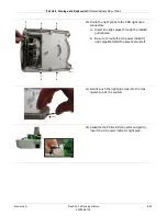
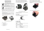
14. Install the new PCB FRU.
a.
Install the five PCB screws.
b.
Insert the two power connectors.
15. Position the replacement Connector Assembly
FRU into the bottom housing.
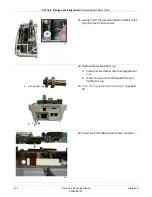
16. Start with the center screw and install the three
connector assembly bracket screws.
17. If the light pipes are to be replaced, route the
light pipes through the bottom housing’s LED
opening.
058A
= step a
b
051A
025A
1
3
2
049A
Summary of Contents for Dash Port 2
Page 1: ...Dash Port 2 Docking Station Service Manual 2000966 138 RevisionA ...
Page 7: ...Revision A Dash Port 2 Docking Station 1 1 2000966 138 1 Introduction ...
Page 8: ...1 2 Dash Port 2 Docking Station Revision A 2000966 138 For your notes ...
Page 15: ...Revision A Dash Port 2 Docking Station 2 1 2000966 138 2 Equipment Overview ...
Page 16: ...2 2 Dash Port 2 Docking Station Revision A 2000966 138 For your notes ...
Page 27: ...Revision A Dash Port 2 Docking Station 3 1 2000966 138 3 Installation ...
Page 28: ...3 2 Dash Port 2 Docking Station Revision A 2000966 138 For your notes ...
Page 41: ...Revision A Dash Port 2 Docking Station 4 1 2000966 138 4 Maintenance ...
Page 42: ...4 2 Dash Port 2 Docking Station Revision A 2000966 138 For your notes ...
Page 59: ...Revision A Dash Port 2 Docking Station 5 1 2000966 138 5 Troubleshooting ...
Page 60: ...5 2 Dash Port 2 Docking Station Revision A 2000966 138 For your notes ...
Page 73: ...Revision A Dash Port 2 Docking Station 6 1 2000966 138 6 Part Lists Drawings and Replacement ...
Page 74: ...6 2 Dash Port 2 Docking Station Revision A 2000966 138 For your notes ...
Page 100: ...A 2 Dash Port 2 Docking Station Revision A 2012659 002 For your notes ...
Page 103: ...Revision A Dash Port 2 Docking Station B 1 2012659 002 B Appendix B Remote Display ...
Page 104: ...B 2 Dash Port 2 Docking Station Revision A 2012659 002 For your notes ...
Page 107: ... ...


