CHAPTER 4: SETPOINTS
CONTROL
869 MOTOR PROTECTION SYSTEM – INSTRUCTION MANUAL
4–343
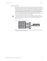
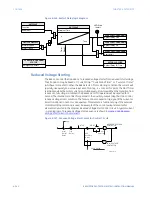
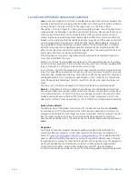
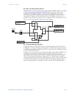
Figure 4-148: Reduced Voltage Start Current Characteristic
NOTE
NOTE:
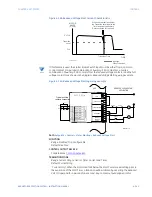
If this feature is used, the Starter Status Switch input must be either from a common
control contact or a parallel combination of Auxiliary ‘52a’ contacts or a 1series
combination of Auxiliary ‘52b’ contacts from the reduced voltage contactor and the full
voltage contactor as shown in the diagram,
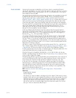
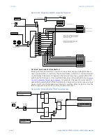
Reduced Voltage Starting wiring example
.
Figure 4-149: Reduced Voltage Starting wiring example
Path:
Setpoints > Control > Motor Starting > Reduced Voltage Start
FUNCTION
Range: Disabled, Trip, Configurable
Default: Disabled
CONTROL OUTPUT RELAY X
For details see
TRANSITION MODE
Range: Current Only, Current or Timer, Current and Timer
Default: Current Only
“Current Only”: When the motor load falls below the Start Current Level setting prior to
the expiration of the Start Timer, a transition will be initiated by asserting the Reduced
Volt Ctrl operand for a period of one second. Any contact output assigned to this
8940
$
1.cdr
MOTOR
AMPS
(% FLA)
When the currrent falls below
the Transition Level and/or the
Timer expires, the Auxiliary
Relay activates for 1 second
Transition Time
TIME
signifies
Open Transition
3 x FLA
Transition
Level
FLA
8940
$
1.cdr
F13
F14
F15
F16
F17
F18
F19
F20
D
IG
ITA
L
IN
PU
TS
DIGITAL INPUT 1
DIGITAL INPUT 2
DIGITAL INPUT 3
DIGITAL INPUT 4
DIGITAL INPUT 5
DIGITAL INPUT 6
DIGITAL INPUT
7
COMMON
SLOT F : I/O_A
F21
+24 V
REDUCED VOLTAGE START
APPLICATION
TRIP
CLOSE/ AUX
START INHIBIT
AUXILIARY
CRITICAL
FAILURE
RELAY
F3
F4
F5
F6
F7
F8
F9
F10
F11
F12
F22
F23
F24
V
V
OU
TP
U
T
R
EL
A
YS
F1
F2
CC 2- 2
Typical auxiliary
contacts connection
CC2
CC2-1
+
CC1
-
869
STOP
START
CC1-1
52a
52b
CC 1-2
CC 1-2
CC 2-2
Summary of Contents for 869
Page 10: ...VIII 869 MOTOR PROTECTION SYSTEM INSTRUCTION MANUAL ...
Page 127: ...CHAPTER 3 INTERFACES SOFTWARE INTERFACE 869 MOTOR PROTECTION SYSTEM INSTRUCTION MANUAL 3 49 ...
Page 129: ...CHAPTER 3 INTERFACES SOFTWARE INTERFACE 869 MOTOR PROTECTION SYSTEM INSTRUCTION MANUAL 3 51 ...
Page 538: ...4 406 869 MOTOR PROTECTION SYSTEM INSTRUCTION MANUAL TESTING CHAPTER 4 SETPOINTS ...
Page 578: ...6 22 869 MOTOR PROTECTION SYSTEM INSTRUCTION MANUAL FLEXELEMENTS CHAPTER 6 METERING ...
Page 592: ...7 14 869 MOTOR PROTECTION SYSTEM INSTRUCTION MANUAL CLEAR RECORDS CHAPTER 7 RECORDS ...

